Resistance, Resistivity & Potential Dividers (Edexcel A Level Physics): Exam Questions

Exam code: 9PH0

40 mins8 questions
1a
Sme Calculator
3 marks

Analogue ammeters were used before digital meters became widely available.

The analogue ammeter shown will measure a maximum current of 1.0 mA and has a resistance of 18 Ω.

q12-nov-2020-9ph0-01-edexcel-as-a-level-phy

The analogue ammeter can be adapted to measure a larger current by adding a resistor, known as a shunt, in parallel with the ammeter. The arrangement is shown below. The analogue ammeter is represented by the 18 Ω resistor.

q12-1-nov-2020-9ph0-01-edexcel-as-a-level-phy

The maximum current through the 18 Ω resistor remains as 1.0 mA.

Show that the shunt would need to have a resistance of about 0.01 Ω to adapt this ammeter to read up to a maximum current of 2.0 A.

1b
Sme Calculator
3 marks

A shunt of this resistance was usually made from Manganin wire.

Calculate the length of Manganin wire of radius 0.95 mm required to make this shunt. resistivity of Manganin = 4.55 × 10⁻⁷ Ω m

Length = ......................................................

2
Sme Calculator
5 marks

Early maglev prototypes used conventional copper electromagnets instead of superconducting electromagnets. Superconductors have zero resistance at low temperatures, meaning no power is wasted by transfer to thermal energy, unlike copper electromagnet systems.

The superconducting electromagnets on the SCMaglev use a liquid helium cooling system which requires a constant power of 25.0 kW.

An engineer suggests that reverting to copper electromagnets operating at an average temperature of 270 K would be more efficient than superconductors because it would remove the need for the cooling system.

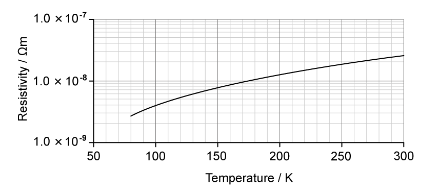
The graph shows the variation of resistivity with temperature for copper.

Graph of resistivity versus temperature from 50–300 K, showing resistivity rising smoothly from about 1×10⁻⁹ to 1×10⁻⁷ Ω m on a logarithmic scale.

Deduce whether the power requirement of the superconductor cooling system is less than the power losses in the copper electromagnet system.

power requirement of the copper electromagnet system = 12.0 MW

operating potential difference = 25.0 kV

total length of copper wire = 1.50 km

cross-sectional area of copper wire = 85.0 mm2

3a
Sme Calculator
3 marks

A “metre bridge” is a circuit which can be used to measure an unknown resistance accurately. The metre bridge includes a metre length of nichrome wire.

Calculate the resistance of a 1.00 m length of the nichrome wire.

resistivity of nichrome = 1.12× 10⁻⁶ Ω m

diameter of wire = 4.00× 10⁻⁴ m

Resistance = ..................................

3b
Sme Calculator
4 marks

This metre length of wire, labelled AB, is connected to a 1.50 V cell of negligible internal resistance and a switch as shown.

q11b-june-2018-9ph0-01-edexcel-as-a-level-phy

i) Explain how the potential along this wire varies with distance from A when the switch is closed.

(2)

ii) Show that the potential difference between A and a point 75.0 cm along the wire from A is about 1.1 V.

(2)

3c
Sme Calculator
2 marks

The metre bridge circuit is shown. The circuit includes a resistor of resistance 3.30 Ω, a very sensitive ammeter and a resistor of unknown resistance R.

q11c-june-2018-9ph0-01-edexcel-as-a-level-phy

A metal slider S can be moved along the nichrome wire and pressed firmly against it to make an electrical connection.

When the switch is closed and S is 75.0 cm along the nichrome wire, the ammeter reads 0 A because the potential difference across the ammeter is zero.

Calculate R.

R = ......................................

4a
Sme Calculator
3 marks

A student is experimenting with different combinations of springs and recalls that in physics it is often possible to model different physical situations in similar ways.

The student suggests that a parallel combination of springs could be a model for a parallel combination of resistors in a circuit.

q6-june-2018-9ph0-03-edexcel-as-a-level-phy

Derive an expression for the effective resistance Reff of two resistors R1 and R2 connected in parallel in a circuit.

4b
Sme Calculator
6 marks

Assess the validity of the student’s suggestion by considering the effective stiffness of two identical springs in parallel.

5a
2 marks

A student designs a light-sensing circuit used to switch on an external circuit when the light intensity falls below a certain level.

The circuit contains a light-dependent resistor (LDR) and a fixed resistor of resistance 10 kΩ, as shown. The output potential difference (p.d.) is connected to an external circuit that contains an LED.

A potential divider circuit with a 6.0 V battery connected in series with a fixed resistor labelled "10 kΩ" and a light-dependent resistor (LDR). Wires connected across the LDR indicate it provides the output potential difference (pd) to an external circuit.

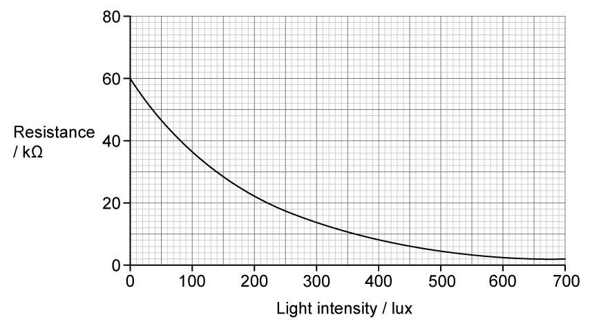
The graph shows how the resistance of the LDR varies with the incident light intensity, measured in lux.

Graph with resistance in kilohms (kΩ) on the y-axis, ranging from 0 to 80, and light intensity in lux on the x-axis, from 0 to 700.  The curve starts at a resistance of 60 kΩ at 0 lux and steadily decreases to around 2 kΩ at 700 lux.

Explain how the resistance of the LDR changes as the incident light intensity decreases.

5b
3 marks

A voltmeter is connected across the fixed resistor.

Explain what happens to the reading on the voltmeter as the incident light intensity decreases.

5c
Sme Calculator
3 marks

The LED in the external circuit switches on when the output p.d. is above 5.0 V.

Determine whether the student's circuit will switch on the LED when the incident light intensity falls below 30 lux.