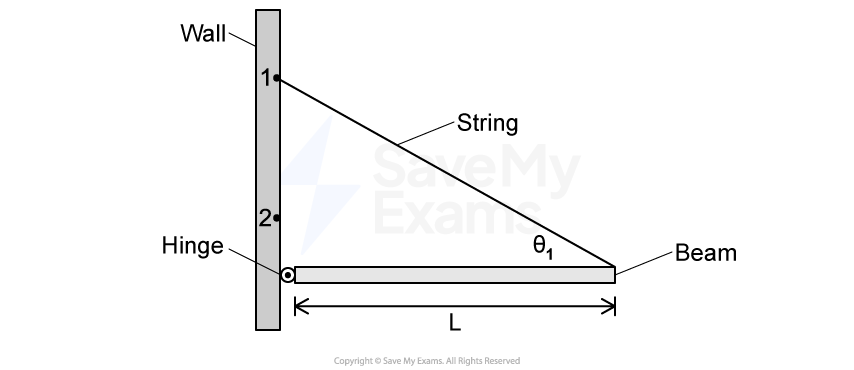
Torque (College Board AP® Physics 1: Algebra-Based): Exam Questions

34 mins19 questions
1
Sme Calculator
3 marks
Diagram of a wall with a hinged beam at point 2. A string forms a diagonal from point 1 on the wall to the beam, creating angle θ1. Length L is noted.

Figure 1

The left end of a uniform beam of mass M and length L is attached to a wall by a hinge, as shown in Figure 1. One end of a string with negligible mass is attached to the right end of the beam. The other end of the string is attached to the wall above the hinge at Point 1. The beam remains horizontal. The hinge exerts a force on the beam of magnitude F subscript H, and the angle between the beam and the string is theta space equals space theta subscript 1.

The following rectangle represents the beam in Figure 1. On the rectangle, draw and label the forces (not components) exerted on the beam. Draw each force as a distinct arrow starting on, and pointing away from, the point at which the force is exerted.

A rectangle representing the beam from Figure 1.

Did this page help you?

2a
Sme Calculator
3 marks
A pulley of mass M and radius R with a block attached to a string hanging from its radius.

Figure 1

A block of unknown mass is attached to a long, lightweight string that is wrapped several turns around a pulley mounted on a horizontal axis through its center, as shown in Figure 1. The pulley is a uniform solid disk of mass M and radius R. The pulley can rotate about its center with negligible friction. The string does not slip on the pulley as the block falls.

When the block is released from rest and as the block travels toward the ground, the magnitude of the tension exerted on the block by the string is F subscript T.

The following circle represents the pulley in Figure 1. On the circle, draw and label the forces (not components) exerted on the pulley after the block is released. Draw each force as a distinct arrow starting on, and pointing away from, the point at which the force is exerted.

A grey circle representing the pulley from Figure 1.
2b
Sme Calculator
2 marks
Diagram comparing two scenarios: a solid disc and a hoop, both with mass M and radius R, under force F_A. The force acts downward in each scenario.

Figure 1

Scenarios 1 and 2 show two different pulleys. In Scenario 1, the pulley is a uniform solid disk of mass M and radius R. In Scenario 2, the pulley is a hoop that has the same mass M and radius R as the disk. Each pulley has a lightweight string wrapped around it several turns and is mounted on a horizontal axle, as shown in Figure 1. Each pulley is free to rotate about its center with negligible friction. In both scenarios, the pulleys begin at rest. Then both strings are pulled with the same constant force F subscript A for the same time interval increment t, causing the pulleys to rotate without the string slipping.

Indicate whether the torque exerted on the hoop is greater than, equal to, or less than the torque exerted on the disk. Justify your reasoning.

Did this page help you?

3a
Sme Calculator
2 marks
A sphere attached to a rod on an axle via a rod. The center of mass of the system is located just below the center of the sphere.

Figure 1

A rod with a sphere attached to the end is connected to a horizontal mounted axle and carefully balanced so that it rests in a position vertically upward from the axle. The center of mass of the rod sphere system is indicated with a circled times, as shown in Figure 1. The sphere is lightly tapped, and the rod-sphere system rotates clockwise with negligible friction about the axle due to the gravitational force.

A student takes a video of the rod rotating from the vertically upward position to the vertically downward position. Figure 2 shows five frames (still shots) that the student selected from the video.

Note: these frames are not equally spaced apart in time.

Five frames illustrating a mechanism with axles and connecting rods in various positions, labelled A to E, showing rotational movement.

Figure 2

In which of the frames of the video in Figure 2 is the magnitude of the torque exerted on the rod-sphere system the greatest? Justify your answer.

3b
Sme Calculator
1 mark
A rod-sphere system hanging vertically downward with respect to the axle. Two lengths are indicated, length "L" represents the distance from axle to the bottom of the sphere, and length "3/4 L" represents the distance from the axle to the center of mass.

Figure 3

The rod-sphere system has mass M and length L, and the center of mass of the rod-sphere system is located a distance 3 over 4 L from the axle, as shown in Figure 3.

Determine an expression for the maximum torque exerted on the rod-sphere system from the moment shown in Frame A to the moment shown in Frame E. Express your answer in terms of M, L, and fundamental constants, as appropriate.

Did this page help you?

4a
Sme Calculator
3 marks
Diagram of a pulley system with two masses. Object 1 mass is \( m_0 \), Object 2 mass is \( 1.5m_0 \). Pulley radii labelled \( r_0 \) and \( 2r_0 \).

Figure 1

Two pulleys with different radii are attached to each other so that they rotate together about a horizontal axle through their common center. There is negligible friction in the axle. Object 1 has mass m subscript 0 and hangs from a light string wrapped around the larger pulley of radius 2 r subscript 0, while Object 2 has mass 1.5 m subscript 0 and hangs from another light string wrapped around the smaller pulley of radius r subscript 0, as shown in Figure 1. At time t space equals space 0, the pulleys are released from rest and the objects begin to accelerate.

The following circles represent the pulleys in Figure 1. On the circles, draw and label arrows that represent the forces (not components) that are exerted on the pulleys after they are released. Draw each force as a distinct arrow starting on and pointing away from the point at which the force is exerted. The lengths of the arrows should reflect the relative magnitudes of the forces exerted at each point.

Two concentric circles with a shared center. Represents the two pulleys in Figure 1.
4b
Sme Calculator
2 marks

Determine an expression for the magnitude of the net torque exerted on the objects-pulleys system about the axle after the pulleys are released in terms of m subscript 0, r subscript 0, and physical constants as appropriate.

4c
Sme Calculator
3 marks

A student makes the following claim:

"The expression for the net torque exerted on the objects-pulleys system must include the tension forces in the strings."

Indicate whether or not the student's claim is correct. Justify your answer.

Did this page help you?