1
1 mark
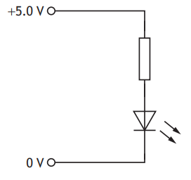
A circuit is set up as shown.
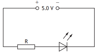
The voltage across the LED is 2.2 V.
The current in the LED is 10.0 mA.
The resistance of resistor R is
0.22 Ω
0.28 Ω
220 Ω
280 Ω
500 Ω
Was this exam question helpful?
Exam code: X857 75
A circuit is set up as shown.
The voltage across the LED is 2.2 V.
The current in the LED is 10.0 mA.
The resistance of resistor R is
0.22 Ω
0.28 Ω
220 Ω
280 Ω
500 Ω
Was this exam question helpful?
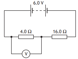
A circuit is set up as shown.
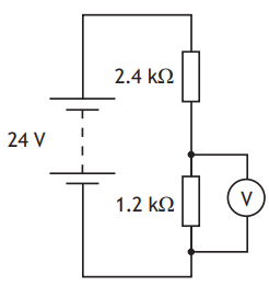
The reading on the voltmeter is
8 V
10 V
16 V
20 V
24 V
Was this exam question helpful?
The graph shows how the voltages across the components P, Q, and R vary with current.
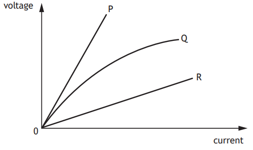
Based on this graph, a group of students make the following statements:
I Component P has a greater resistance than component R.
II Component R has a greater resistance than component Q.
III Component Q has a resistance that decreases as the current increases.
Which of these statements is/are correct?
I only
II only
III only
I and III only
II and III only
Was this exam question helpful?
A ceramic power resistor is a common type of resistor, used in circuits to dissipate large amounts of energy as heat. They are labelled with a power rating and resistance value.
Two examples are shown.
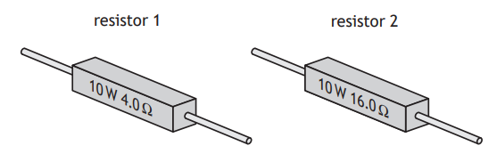
State which of the two resistors will allow the greater current to pass.
You must justify your answer.
The resistors are connected in the circuit shown.
Calculate the reading on the voltmeter.
Was this exam question helpful?
The graph shows how the resistance R of a thermistor varies with temperature T.

The thermistor is connected in a circuit.
At a temperature of 50 °C the current in the thermistor is 0∙004 A.
At this temperature the voltage across the thermistor is
0·000 02 V
0·002 V
0·008 V
8 V
500 V
Was this exam question helpful?
A student is investigating how the length of a wire affects its resistance.
The student connects different lengths of wire to a power supply of fixed voltage and measures the current in each length of wire.
The measurements taken by the student are shown in the table.
Length of wire (m) | Current (A) |
0.20 | 0.94 |
0.40 | 0.66 |
0.60 | 0.47 |
0.80 | 0.37 |
1.00 | 0.32 |
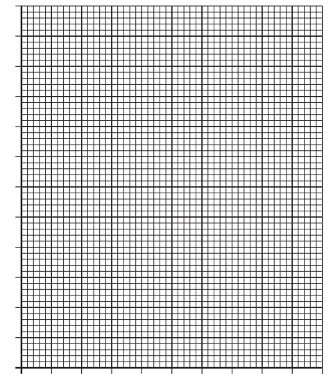
(i) Using the graph paper, draw a graph of these measurements.
[3]
(ii) State whether the resistance of the wire increases, decreases or stays the same, as the length of wire increases.
Justify your answer.
[2]
(iii) Use your graph to predict the current in a 0·50 m length of wire, when connected to the power supply.
[1]
(iv) Suggest one way in which the experimental procedure could be improved to give more reliable results.
[1]
A length of the wire with a resistance of 5·2 Ω is then folded into a rectangular shape and the ends are joined together.
An ohmmeter is connected across the wire between point X and point Y as shown.
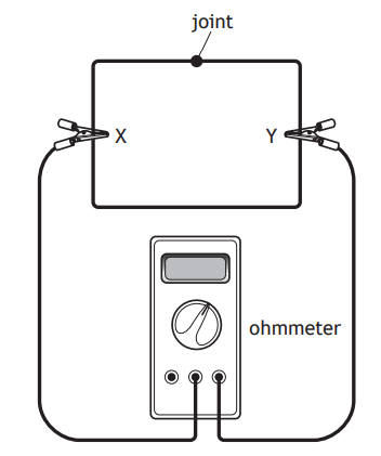
State whether the reading on the ohmmeter would be less than, equal to or greater than 5·2 Ω.
You must justify your answer.
Was this exam question helpful?
A wireless charger uses radio waves to charge the battery of a mobile phone.
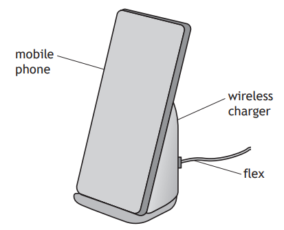
The charger is connected to a direct current (d.c.) supply via a flex.
Once the mobile phone is fully charged, an LED on the charger lights.
Part of the circuit containing the LED is shown.
The voltage across the LED is 2.2 V and the current in the LED is 18 mA.
Determine the resistance of the resistor in series with the LED.
Was this exam question helpful?
A student sets up the following circuit to investigate the relationship between the current in and the voltage across a lamp.
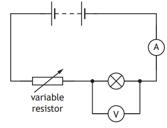
The student uses the circuit to obtain a range of measurements of current in the lamp and voltage across the lamp.
The measurements taken by the student are shown in the table.
Current (A) | Voltage (V) |
0.20 | 0.8 |
0.40 | 2.3 |
0.60 | 4.9 |
0.80 | 8.6 |
0.90 | 11.0 |
(i) Using the graph paper, draw a graph of the student’s results.
[3]
(ii) Use your graph to determine the voltage across the lamp when the current in the lamp is 0.70 A.
[1]
(iii) Describe how the student obtained a range of values of current and voltage using this circuit.
[1]
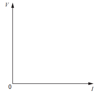
The student then replaces the lamp in the circuit with a fixed resistor and repeats the investigation.
Using the axes below, sketch a graph to show how the voltage V across the fixed resistor varies with the current I in the circuit.
Was this exam question helpful?
A solar jar is designed to collect energy from the Sun during the day and release this energy as light at night.
When the solar jar is placed in sunlight, photovoltaic cells on the lid are used to charge a rechargeable battery.
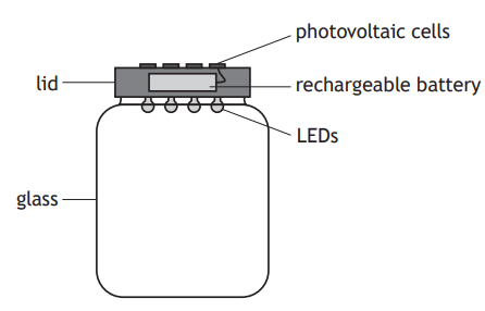
At night, the rechargeable battery is used to power four identical LEDs.
Part of the circuit in the solar jar is shown.
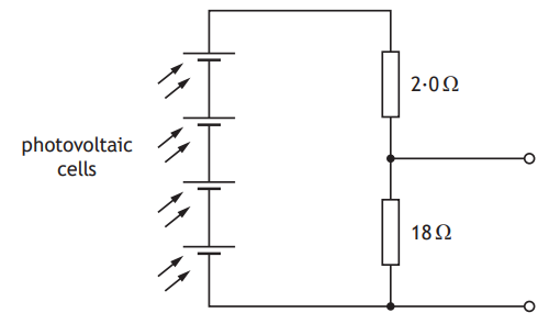
In direct sunlight the photovoltaic cells produce a combined voltage of 4∙0 V.
Calculate the voltage across the 18 Ω resistor.
Another part of the circuit containing the LEDs is shown.
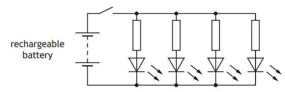
The switch is now closed and the LEDs light.
(i) State the purpose of the resistor connected in series with each LED.
[1]
(ii) After a few hours the rechargeable battery produces a voltage of 3·4 V.
At this point in time the voltage across each LED is 1·6 V and the current in each LED is 25 mA.
Determine the value of the resistor in series with each LED.
[4]
Was this exam question helpful?