1
1 mark
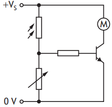
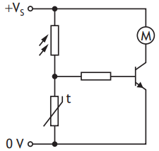
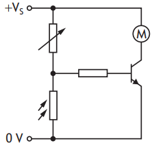
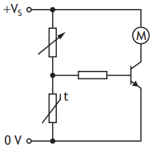
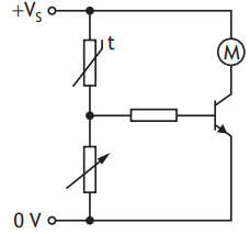
A circuit containing an LDR switches on a motor when the light level drops below a certain value.
The resistance of the LDR increases as the light level decreases.
Which of the following shows this circuit?
Was this exam question helpful?
Exam code: X857 75
A circuit containing an LDR switches on a motor when the light level drops below a certain value.
The resistance of the LDR increases as the light level decreases.
Which of the following shows this circuit?
Was this exam question helpful?
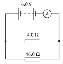
A student sets up the following circuit.
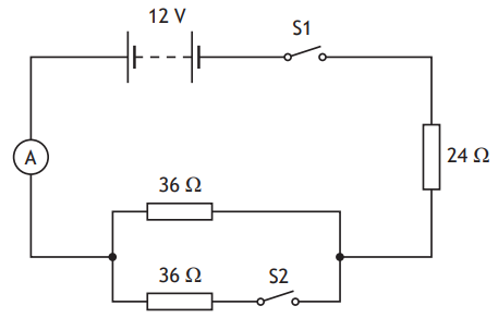
Initially, both switch S1 and switch S2 are open
The student closes switch S1.
Determine the reading on the ammeter.
The student now also closes switch S2.
(i) Determine the total resistance of this circuit.
[4]
(ii) State whether the reading on the ammeter will now be less than, equal to or greater than the value determined in (a).
You must justify your answer.
[2]
Was this exam question helpful?
A capacitor consisting of two parallel metal plates, X and Y, is connected in a circuit as shown.
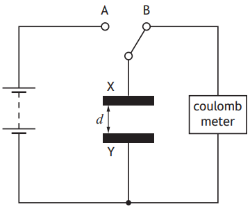
The distance d between plate X and plate Y can be adjusted.
The capacitor is initially uncharged.
The switch is moved to position A and charge is transferred to the capacitor.
The switch is now moved to position B and the charge Q stored on the capacitor is measured by the coulombmeter.
This process is repeated for a range of different distances d between plate X and plate Y.
The charge Q stored on the capacitor for a range of different distances d between plate X and plate Y is shown in the table.
d (mm) | Q (×10−12 C) |
10 | 178 |
20 | 90 |
30 | 62 |
40 | 47 |
50 | 37 |
(i) Using the graph paper, draw a graph of these results.
[3]

(ii) Use your graph to determine the charge stored on the capacitor when the distance between plate X and plate Y is 25 mm.
[1]
Suggest two ways in which the experimental procedure could be improved.
Was this exam question helpful?
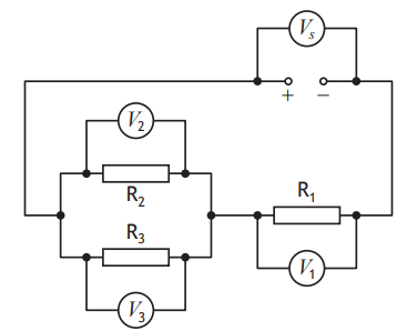
A circuit is set up as shown.
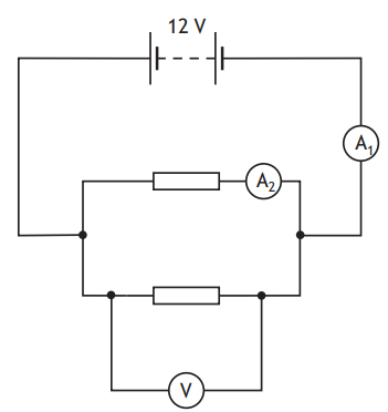
The resistors are identical.
Which row in the table shows the reading on the voltmeter and possible readings on ammeters A1 and A2?
Reading on voltmeter (V) | Reading on ammeter A1 (A) | Reading on ammeter A2 (A) | |
A | 6 | 0.3 | 0.3 |
B | 6 | 0.6 | 0.3 |
C | 12 | 0.3 | 0.3 |
D | 12 | 0.3 | 0.6 |
E | 12 | 0.6 | 0.3 |
Was this exam question helpful?
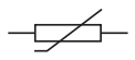
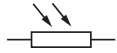
Which of the following symbols represents a thermistor?

Was this exam question helpful?
Two resistors are connected in a circuit as shown.
(i) Calculate the total resistance of the circuit.
[3]
(ii) Another ceramic power resistor is now connected in parallel with the two resistors in the circuit.
State the effect this change has on the reading on the ammeter.
Justify your answer.
[2]
Was this exam question helpful?
A dehumidifier is an appliance that extracts water from the air around it.
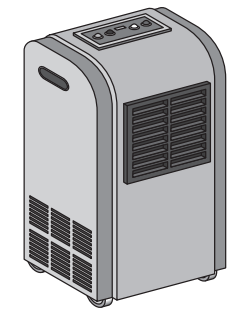
One particular dehumidifier operates at 230 V a.c. and has a power rating of 0.35 kW.
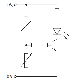
The dehumidifier switches on automatically when the moisture in the air increases above a certain level. This causes an LED to light and a fan to turn on.
Part of the circuit diagram for the circuit is shown.
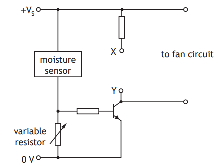
(i) Complete the circuit diagram to show the LED connected correctly between X and Y.
[1]
(ii) The voltage across the moisture sensor decreases as the moisture in the air increases.
Explain how the circuit operates to turn on the LED when the moisture in the air increases above a certain level.
[2]
(iii) Explain the purpose of the variable resistor in this circuit.
[1]
Was this exam question helpful?
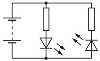
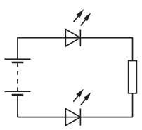
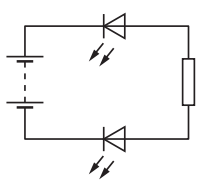
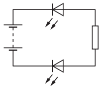
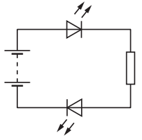
A student sets up the circuits shown.
In which circuit will both LEDs be lit?
Was this exam question helpful?
A circuit is set up as shown.
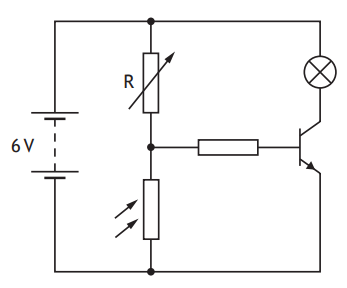
The room temperature is 20 °C.
The lamp is off.
The lamp will light when
the light level is decreased below a certain value
the light level is increased above a certain value
the resistance of R is increased above a certain value
the battery voltage is reduced to 5 V
the temperature is increased above a certain value
Was this exam question helpful?
A circuit is set up as shown.
A student makes the following statements about the readings on the voltmeters.
I ![]()
II ![]()
III ![]()
Which of these statements must always be true?
II only
I and II only
I and III only
II and III only
I, II and III
Was this exam question helpful?
A circuit is set up as shown.
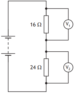
The reading on voltmeter V1 is 3.6 V.
The reading on voltmeter V2 is
0.4 V
2.2 V
2.4 V
3.6 V
5.4 V
Was this exam question helpful?
A circuit is set up as shown.
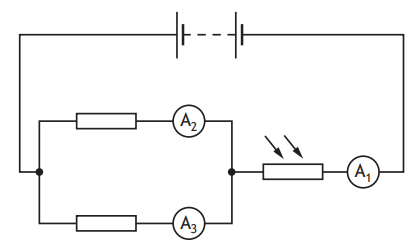
The resistance of the LDR increases as the light level decreases.
The light level incident on the LDR decreases.
Which row in the table describes the effect of this change on the readings on the ammeters?
Reading on ammeter A1 | Reading on ammeter A2 | Reading on ammeter A3 | |
A | decreases | decreases | decreases |
B | decreases | stays the same | stays the same |
C | stays the same | stays the same | stays the same |
D | increases | stays the same | stays the same |
E | increases | increases | increases |
Was this exam question helpful?
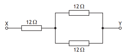
Three resistors are connected as shown.
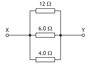
The total resistance between X and Y is
0.5 Ω
2.0 Ω
4.0 Ω
6.0 Ω
22 Ω
Was this exam question helpful?
A wireless charger uses radio waves to charge the battery of a mobile phone.
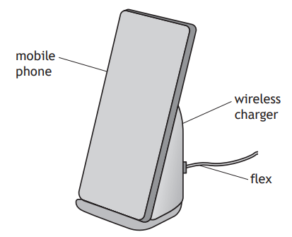
The charger is connected to a direct current (d.c.) supply via a flex.
During use the charger heats up.
The charger contains a fan that switches on automatically when the temperature of the charger increases above a certain level.
Part of the circuit containing the fan is shown.
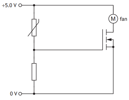
As the temperature of the charger increases, the resistance of the thermistor decreases.
Explain how the circuit operates to switch on the fan when the temperature of the charger increases above a certain level.
Was this exam question helpful?
A transistor switching circuit is set up as shown.
The variable resistor is adjusted until the LED switches off.
The temperature of the thermistor is now increased.
The resistance of the thermistor decreases as the temperature increases.
Which row in the table describes the effect of this change on the voltage across the thermistor, the voltage across the variable resistor, and whether the LED stays off or switches on?
Voltage across the thermistor | Voltage across the variable resistor | LED | |
A | decreases | increases | switches on |
B | decreases | decreases | switches on |
C | decreases | decreases | stays off |
D | increases | decreases | stays off |
E | increases | increases | switches on |
Was this exam question helpful?
Three resistors are connected as shown.
The resistance between X and Y is
4 Ω
6 Ω
18 Ω
24 Ω
36 Ω
Was this exam question helpful?