Transistors (SQA National 5 Physics): Revision Note
Exam code: X857 75

Transistors
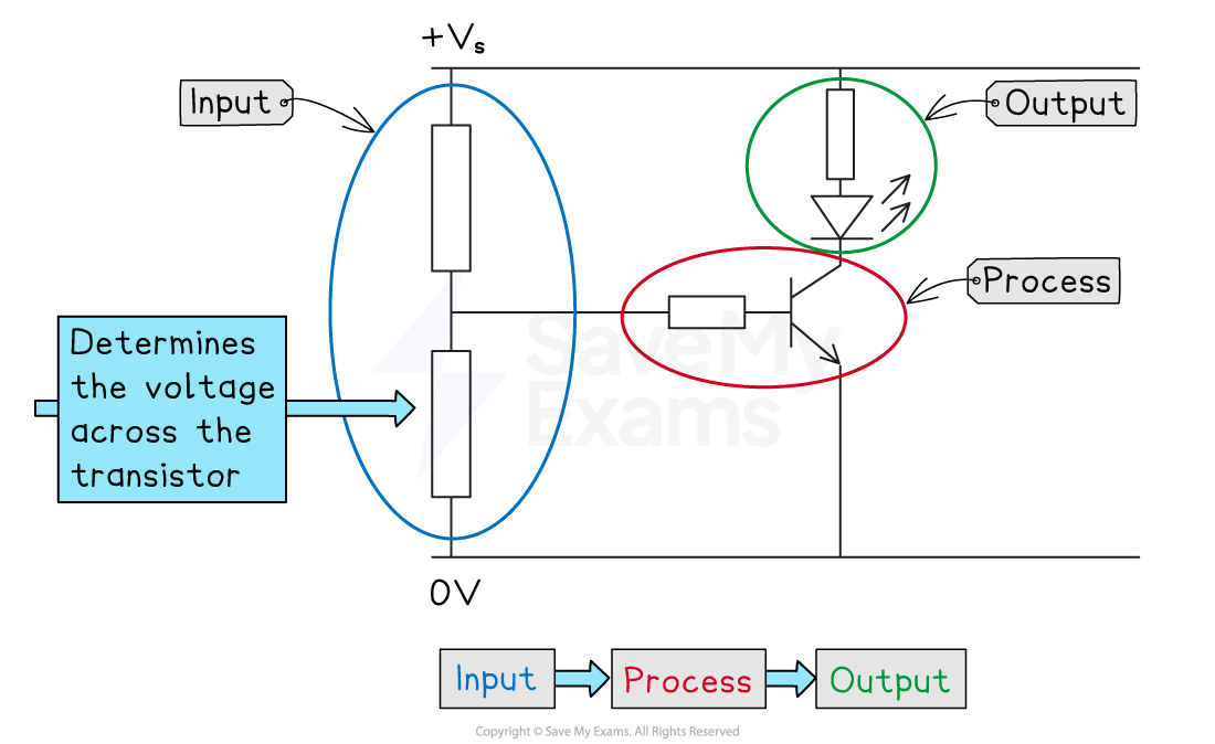
Electronic systems
Electronic systems consist of three parts
Input
Process
Output
Information is passed along the system by electrical signals
![]()
Input devices detect or measure changes in the surroundings and produce an electrical signal to be processed
Switch - allows current to flow when closed
Microphone - produces a voltage when the sound level increases
Photovoltaic cell - produces a voltage when light intensity increases
Thermistor - resistance decreases when the temperature increases
Light-dependent resistor (LDR) - resistance decreases when the light level increases
Output devices transform electrical energy into a useful form of energy
Lamp - converts electrical energy to light
LED - converts electrical energy to light
Loudspeaker - converts electrical energy to sound
Motor - converts electrical energy to kinetic energy
Relay - converts electrical energy to kinetic energy
Process devices operate as an electronic switch between the input and output devices
This is the job of the transistor
What is a transistor?
A transistor is an electronic switch
It switches on when the input voltage reaches a certain value
There are two types
npn transistor
MOSFET transistor
Both types have three connections
An npn transistor switches on at around 0.7 V
ON: If the input voltage across the base exceeds 0.7 V, current flows from collector to emitter
OFF: If the input voltage does not exceed 0.7 V, current cannot flow through the output
A MOSFET transistor switches on at around 2.0 V
ON: If the input voltage across the gate exceeds 2.0 V, current flows from source to drain
OFF: If the input voltage does not exceed 2.0 V, current cannot flow through the output
npn and MOSFET transistor symbols

Transistor switching circuits
A transistor switching circuit is used to represent an electronic system
All switching circuits follow input → process → output
Input = a potential divider made from a sensor (e.g. LDR or thermistor) and a resistor (usually variable)
Process = a transistor (npn or MOSFET)
Output = device to be switched on or off (e.g. LED, motor, relay)
Basic set-up of a switching circuit
Light-controlled circuits
Light-controlled circuits use an LDR and a variable resistor as the input
Consider a circuit connected to an LED as the output:
When the light level decreases (gets darker), the resistance of the LDR increases, and the voltage across the LDR increases
With the LDR as the lower component of the divider, the voltage across the transistor increases
When the voltage exceeds the threshold (0.7 V for npn), the transistor conducts and current flows to the LED, switching it on
An npn transistor circuit with an LDR
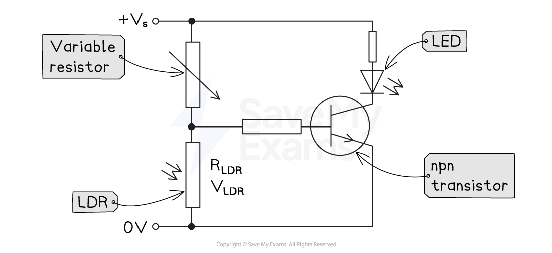
Function of the circuit: the LED switches ON when the light level gets too low
If the LDR and the variable resistor were swapped, it would invert the behaviour (i.e. the LED would switch OFF when the light level gets too low)
Function of the variable resistor: controls the light level at which the transistor switches on
For example, increasing the resistance of the variable resistor would decrease the share of the supply voltage across the LDR
The LED would switch on at a lower light level (i.e. dimmer) than before, as the resistance of the LDR would need to be greater to switch on the transistor
Operation of an LDR switching on an LED

Temperature-controlled circuits
Temperature-controlled circuits use a thermistor and a variable resistor as the input
Consider a circuit connected to a relay and a heating circuit as the output:
When the temperature decreases (gets colder), the resistance of the thermistor increases, and the voltage across the thermistor increases
With the thermistor as the lower component of the divider, the voltage across the transistor increases
When the voltage exceeds the threshold (2.0 V for MOSFET), the transistor conducts and a current flows to the relay coil
This closes the relay switch and allows a current to flow in the heater circuit, switching the heater on
A MOSFET transistor circuit with a thermistor
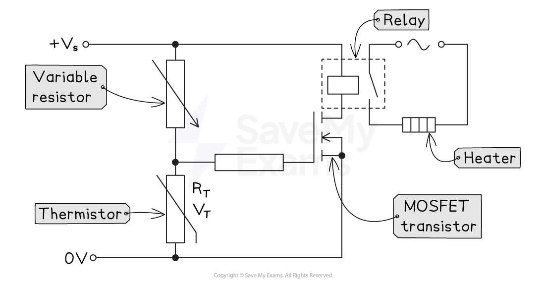
Function of the circuit: the heater switches ON when the temperature gets too low
If the thermistor and the variable resistor were swapped, it would invert the behaviour (i.e. with a fan instead of a heater; the fan would switch OFF when the temperature gets too low)
Function of the variable resistor: controls the temperature at which the transistor switches on
For example, increasing the resistance of the variable resistor would decrease the share of the supply voltage across the thermistor
The heater would switch on at a lower temperature than before, as the resistance of the thermistor would need to be greater to switch on the transistor
Operation of a thermistor switching on a heater

Examiner Tips and Tricks
Common exam questions on this topic tend to include:
Identifying the components in a switching circuit
Explaining how a switching circuit operates
Remember: LURD = light up resistance down, and TURD = temperature up resistance down
Potential divider calculations
e.g. calculating the voltage of a sensor at a given condition, or rearranging to find the resistance of the sensor required for switching
The role of the variable resistor
To control the condition (light level/temperature) at which the transistor (and therefore the output) switches on or off
The effect of swapping the sensor and resistor
It inverts the behaviour (e.g., hot-activated fan instead of cold-activated heater; light-activated vs dark-activated lamp)

Unlock more, it's free!
Join the 100,000+ Students that ❤️ Save My Exams
the (exam) results speak for themselves:

Was this revision note helpful?