Components in Series & Parallel Circuits (Edexcel GCSE Physics): Exam Questions

Exam code: 1PH0

2 hours11 questions
1a
Sme Calculator
2 marks

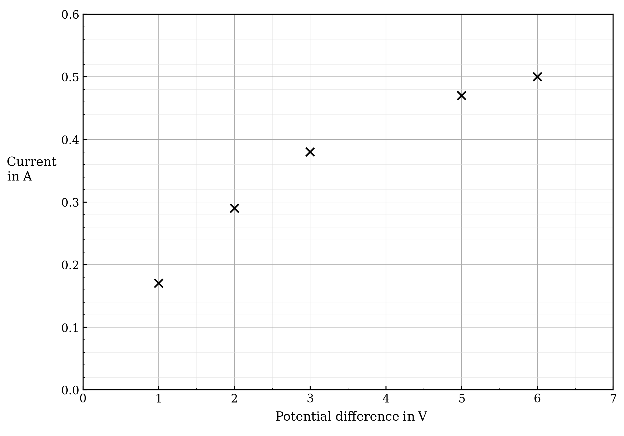
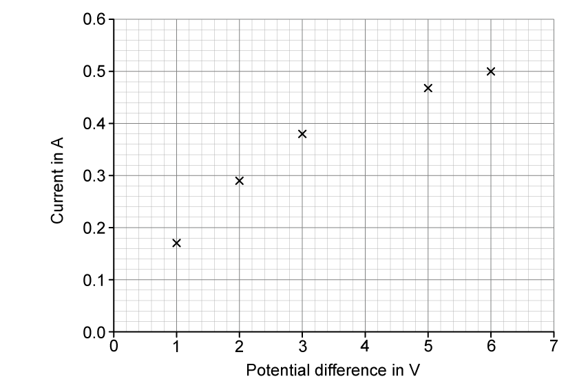
The graphs in Figure 1 show how the current in a component changes with the voltage applied across the component. 

Draw a line from each component to its correct graph.

9qLBfB3i_10-2-e-1a-circuit-diagrams-and-graphs

Figure 1

1b
Sme Calculator
2 marks

Describe how the resistance of a light-dependent resistor (LDR) varies with light intensity.

1c
Sme Calculator
1 mark

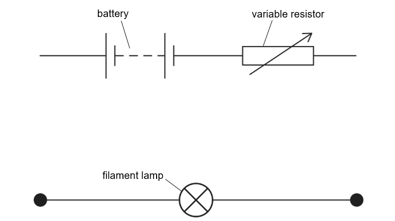
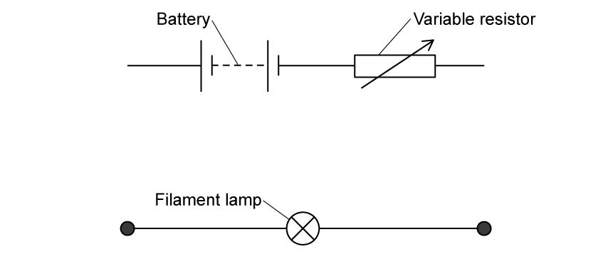
Figure 1 shows the symbol for an electrical component.

10-2-e-1c-thermistory-circuit-symbol

Figure 1

 State the name of the component shown in Figure 1.

1d
Sme Calculator
2 marks

Describe how the resistance of a thermistor varies with a change of temperature.

2a
Sme Calculator
4 marks

Ohmic conductors are conductors that have a fixed resistance. 

State which of the following are non-ohmic conductors.

Diode

Thermistor

Filament lamp

LDR

Resistor

2b
Sme Calculator
1 mark

Which of the following is true?

  • If two resistors are in series, their net resistance is decreased

  • If two resistors are in parallel, their net resistance in increased

  • If two resistors are in series or parallel, their net resistance is increased

  • If two resistors are in parallel, their net resistance is decreased

2c
Sme Calculator
1 mark

Figure 1 shows how the current varies with a potential difference for a filament lamp.

q3teC-Yz_10-2-e-2c-filament-lamp-example

Figure 1

State what the gradient of the graph represents.

2d
Sme Calculator
3 marks

Calculate the resistance of the lamp when the potential difference is 3.0 V.

3a
Sme Calculator
2 marks

Figure 1 shows a series circuit connecting a battery of potential difference 24 V, a filament lamp and a resistor.

10-2-e-3a-series-circuit

Figure 1

Sketch the circuit with the lamp and resistor in parallel instead.

3b
Sme Calculator
1 mark

The lamp and resistor have the same resistance.

Determine the potential difference in the lamp and resistor when connected in Figure 1.

3c
Sme Calculator
1 mark

State a component that could be added to Figure 1 to change the current in the circuit.

3d
Sme Calculator
2 marks

The lamp in Figure 1 is now replaced with an LED to test and measure its output with changing light intensity. 

Sketch the circuit symbol for the LED on Figure 2. 

10-2-e-3d-series-circuit-missing-led

Figure 2

4a
2 marks

A student investigates how the current in a filament lamp changes as the potential difference across it is varied.

Figure 3 shows the apparatus used for this investigation.

Partial circuit diagram showing a battery, a variable resistor, and a filament lamp. The battery and variable resistor are connected in series, but they are not connected to the filament lamp.

Figure 3

Complete the circuit in Figure 3 by adding:

  • an ammeter to measure the current in the lamp

  • a voltmeter to measure the potential difference across the lamp

4b
3 marks

The student records the following results.

Potential difference (V)

Current (A)

1.0

0.17

2.0

0.29

3.0

0.38

4.0

0.44

5.0

0.47

6.0

0.50

Figure 4 shows a graph with five of the data points already plotted.

Graph with current in amps on the y-axis ranging from 0 to 0.60 with divisions of 0.05 and potential difference in volts on the x-axis ranging from 0 to 7.0 with divisions of 1.0. Five data points already plotted as crosses at (1.0, 0.17), (2.0, 0.29), (3.0, 0.38), (5.0, 0.47) and (6.0, 0.50).

Figure 4

(i) The highlighted row in the table has not been plotted. Plot this point on Figure 4.

[1]

(ii) Draw a best fit curve on the graph in Figure 4.

[1]

(iii) Use the graph in Figure 4 to estimate the current through the filament lamp when the potential difference is 2.5 text  V end text.

[1]

4c
Sme Calculator
2 marks

The student writes this conclusion:

"The current is directly proportional to the potential difference."

Comment on the student's conclusion.

Use data to support your answer.

4d
2 marks

The student replaces the filament lamp with an electric heater. The heater draws a much larger current than the filament lamp.

Explain why the connecting wires used with the heater should be thicker than those used with the filament lamp.

1a
Sme Calculator
8 marks

A student investigates resistors connected in parallel using a number of resistors.

Each resistor has the same resistance.

Figure 19 shows a circuit diagram with one resistor, R.

fig-19-paper2h-june2020-edexcel-gcse-physics

Figure 19

(i) Add to Figure 19:

  • a voltmeter to find the potential difference across resistor R

  • another resistor in parallel with resistor R.

[2]

(ii) State the measurements that the student must take to find the overall resistance of the resistors in parallel.

[2]

(iii) The student investigates how the overall resistance of the circuit changes when additional resistors are added in parallel to R.

Each resistor has the same resistance. Figure 20 shows the results of the student’s investigation.

fig-20-paper2h-june2020-edexcel-gcse-physics

Figure 20

State the resistance of a single resistor.

resistance = .............................................................. Ω[1]

(iv) Comment on the relationship between the overall resistance of the circuit and the number of resistors in parallel.

Use information from Figure 20 to support your answer.

[3]

1b
Sme Calculator
4 marks

A different circuit is then set up with two resistors as shown in Figure 21.

fig-21-paper2h-june2020-edexcel-gcse-physics

Figure 21

i) Calculate the potential difference across the 15 Ω resistor.

potential difference = ......................................... V[2]

ii) Calculate the total power dissipated when there is a current of 0.20 A in the two resistors.

Use the equation

P = I2 × R

power produced ............................................ W[2]

2a
5 marks

Figure 18 shows identical filament lamps connected together to a 12V power supply.

fig-18-paper2h-june2018-edexcel-gcse-physics

Figure 18

(i) Calculate the potential difference across each lamp.

potential difference = ............................................... V[1]

(ii) The power output of each lamp is 0.75W

Calculate the resistance of each lamp.

resistance = ............................................... Ω[4]

2b
6 marks

Explain, with the aid of a circuit diagram, the method a student could use to investigate how the resistance of a single lamp changes with the potential difference across the lamp.

3a
2 marks

A student is investigating the I-V characteristic of a filament bulb. Figure 1 shows the circuit they set up to conduct the investigation.

2-1-h-1a-incorrect-circuit

Figure 1

The circuit shown in Figure 1 will not provide valid results. 

Identify one error the student has made and state how to rectify it.

3b
5 marks

The student plotted the graph shown in Figure 2 from her data.

2-1-h-1c-iv-characteristics-filament-graph

Figure 2

Use words from the box to complete the following sentences.

increase

decrease

increases

decreases

As the potential difference increases, the current ............................., but the rate at which this occurs .............................This is because the temperature of the filament in the bulb ............................. with current.So the resistance ............................. causing the current to .............................

3c
1 mark

Which of the following steps is not a suitable safety procedure for this investigation?

  • Keep liquids away from the equipment

  • Tie long hair back

  • Turn off the power supply if burning is smelled

  • Take care when handling the hot filament bulbs

3d
4 marks

Use the graph shown in Figure 2 to calculate the resistance of the filament lamp when the potential difference is 3 V.

Give your answer to an appropriate number of significant figures.

2-1-h-1c-iv-characteristics-filament-graph

Figure 2

  resistance of filament lamp = .................................... Ω

4a
1 mark

Draw the circuit symbol for a light-dependent resistor (LDR).

4b
1 mark

Which of the following sketch graphs shows the IV characteristic of an LDR?

square  A

square  B

graph-a
graph-b

square  C

square  D

graph-c
graph-d
    4c
    2 marks

    Explain how the shape of the graph in part (b) shows that the LDR is an ohmic conductor.

    4d
    1 mark

    LDRs are used as light sensors to turn on lights as it gets dark outside.

    Describe how the resistance of an LDR varies with light intensity.

    5a
    4 marks

    Some students in a physics class are investigating the I-V characteristics of a fixed resistor.

    The students are given the following equipment:

    • An ammeter

    • A voltmeter

    • A variable resistor

    • Fixed resistors of 100 Ω, 200 Ω, 400  and 500 Ω

    • A power pack

    • Wires

    Draw a circuit using the equipment from the list that would enable the students to gather valid data.

    5b
    5 marks

    Describe a method that would allow the students to obtain valid results.

    5c
    1 mark

    The students plotted their data and produced the graph shown in Figure 1.

    2-1-m-5c-iv-characteristics-graph

    Figure 1

    Write down an expression for the gradient of the graph in terms of resistance.

    5d
    4 marks

    Use the graph to determine the resistance of the fixed resistor used by the students.

       resistance = .................................... Ω

    6a
    Sme Calculator
    3 marks

    Figure 11 shows four appliances connected in parallel to the mains supply.

    A parallel circuit showing four branches connected to the mains supply. Branch 1 contains a microwave labelled "4.8 A". Branch 2 contains a TV labelled "0.40 A". Branch 3 contains a toaster labelled "10 A". Branch 4 contains a lamp labelled "0.20 A".

    Figure 11

    (i) Calculate the total current drawn from the mains supply when all four appliances are switched on.

    [2]

    (ii) State how the overall resistance of the circuit changes when any one of the appliances is switched off.

    [1]

    6b
    1 mark

    Suggest one advantage of connecting the appliances in parallel instead of in series.

    1a
    2 marks

    A student investigates how the current in a filament lamp changes as the potential difference across it is varied.

    Figure 13 shows the apparatus used for this investigation.

    Partial circuit diagram showing a battery, a variable resistor, and a filament lamp. The battery and variable resistor are connected in series, but they are not connected to the filament lamp.

    Figure 13

    Complete the circuit in Figure 13 by adding:

    • an ammeter to measure the current in the lamp

    • a voltmeter to measure the potential difference across the lamp

    1b
    3 marks

    The student records the following results.

    Potential difference (V)

    Current (A)

    1.0

    0.17

    2.0

    0.29

    3.0

    0.38

    4.0

    0.44

    5.0

    0.47

    6.0

    0.50

    Figure 14 shows a graph with five of the data points already plotted.

    Graph with current in amps on the y-axis ranging from 0 to 0.60 with divisions of 0.05 and potential difference in volts on the x-axis ranging from 0 to 7.0 with divisions of 1.0. Five data points already plotted as crosses at (1.0, 0.17), (2.0, 0.29), (3.0, 0.38), (5.0, 0.47) and (6.0, 0.50).

    Figure 14

    (i) The highlighted row in the table has not been plotted. Plot this point on Figure 14.

    [1]

    (ii) Draw a best fit curve on the graph in Figure 14.

    [1]

    (iii) Use the graph in Figure 14 to estimate the current through the filament lamp when the potential difference is 2.5 text  V end text.

    [1]

    1c
    Sme Calculator
    2 marks

    The student writes this conclusion:

    "The current is directly proportional to the potential difference."

    Comment on the student's conclusion.

    Use data to support your answer.

    1d
    3 marks

    Explain why the resistance of the filament lamp changes as the potential difference across it increases.