Truth Tables (Cambridge (CIE) IGCSE Computer Science): Revision Note
Exam code: 0478 & 0984

Truth Tables
What is a truth table?
A truth table is a tool used in logic and computer science to visualise the results of Boolean expressions
They represent all possible inputs and the associated outputs for a given Boolean expression
AND
Circuit symbol | Truth Table | |||||||||||||||
|---|---|---|---|---|---|---|---|---|---|---|---|---|---|---|---|---|
 |
|
OR
Circuit symbol | Truth Table | |||||||||||||||
|---|---|---|---|---|---|---|---|---|---|---|---|---|---|---|---|---|
 |
|
NOT
Circuit symbol | Truth Table | ||||||
|---|---|---|---|---|---|---|---|
 |
|
XOR (exclusive)
Circuit symbol | Truth Table | |||||||||||||||
|---|---|---|---|---|---|---|---|---|---|---|---|---|---|---|---|---|
 |
|
NAND (not and)
Circuit symbol | Truth Table | |||||||||||||||
|---|---|---|---|---|---|---|---|---|---|---|---|---|---|---|---|---|
 |
|
NOR (not or)
Circuit symbol | Truth Table | |||||||||||||||
|---|---|---|---|---|---|---|---|---|---|---|---|---|---|---|---|---|
 |
|
Truth Tables for Logic Circuits
How do you create truth tables for logic circuits?
To create a truth table for the expression P = (A AND B) AND NOT C
Calculate the numbers of rows needed (2number of inputs)
In this example there are 3 inputs (A, B, C) so a total of 8 rows are needed (23)
To not miss any combination of inputs, start with 000 and count up in 3-bit binary (0-7)
A | B | C |
|---|---|---|
0 | 0 | 0 |
0 | 0 | 1 |
0 | 1 | 0 |
0 | 1 | 1 |
1 | 0 | 0 |
1 | 0 | 1 |
1 | 1 | 0 |
1 | 1 | 1 |
Add a new column to show the results of the brackets first (A AND B)
A | B | C | A AND B |
|---|---|---|---|
0 | 0 | 0 | 0 |
0 | 0 | 1 | 0 |
0 | 1 | 0 | 0 |
0 | 1 | 1 | 0 |
1 | 0 | 0 | 0 |
1 | 0 | 1 | 0 |
1 | 1 | 0 | 1 |
1 | 1 | 1 | 1 |
Add a new column to show the results of NOT C
A | B | C | A AND B | NOT C |
|---|---|---|---|---|
0 | 0 | 0 | 0 | 1 |
0 | 0 | 1 | 0 | 0 |
0 | 1 | 0 | 0 | 1 |
0 | 1 | 1 | 0 | 0 |
1 | 0 | 0 | 0 | 1 |
1 | 0 | 1 | 0 | 0 |
1 | 1 | 0 | 1 | 1 |
1 | 1 | 1 | 1 | 0 |
The last column shows the result of the Boolean expression (P) by comparing (A AND B) AND NOT C //
format('truetype')%3Bfont-weight%3Anormal%3Bfont-style%3Anormal%3B%7D%40font-face%7Bfont-family%3A'round_brackets18549f92a457f2409'%3Bsrc%3Aurl(data%3Afont%2Ftruetype%3Bcharset%3Dutf-8%3Bbase64%2CAAEAAAAMAIAAAwBAT1MvMjwHLFQAAADMAAAATmNtYXDf7xCrAAABHAAAADxjdnQgBAkDLgAAAVgAAAASZ2x5ZmAOz2cAAAFsAAABJGhlYWQOKih8AAACkAAAADZoaGVhCvgVwgAAAsgAAAAkaG10eCA6AAIAAALsAAAADGxvY2EAAARLAAAC%2BAAAABBtYXhwBIgEWQAAAwgAAAAgbmFtZXHR30MAAAMoAAACOXBvc3QDogHPAAAFZAAAACBwcmVwupWEAAAABYQAAAAHAAAGcgGQAAUAAAgACAAAAAAACAAIAAAAAAAAAQIAAAAAAAAAAAAAAAAAAAAAAAAAAAAAAAAAAAAAACAgICAAAAAo8AMGe%2F57AAAHPgGyAAAAAAACAAEAAQAAABQAAwABAAAAFAAEACgAAAAGAAQAAQACACgAKf%2F%2FAAAAKAAp%2F%2F%2F%2F2f%2FZAAEAAAAAAAAAAAFUAFYBAAAsAKgDgAAyAAcAAAACAAAAKgDVA1UAAwAHAAA1MxEjEyMRM9XVq4CAKgMr%2FQAC1QABAAD%2B0AIgBtAACQBNGAGwChCwA9SwAxCwAtSwChCwBdSwBRCwANSwAxCwBzywAhCwCDwAsAoQsAPUsAMQsAfUsAoQsAXUsAoQsADUsAMQsAI8sAcQsAg8MTAREAEzABEQASMAAZCQ%2FnABkJD%2BcALQ%2FZD%2BcAGQAnACcAGQ%2FnAAAQAA%2FtACIAbQAAkATRgBsAoQsAPUsAMQsALUsAoQsAXUsAUQsADUsAMQsAc8sAIQsAg8ALAKELAD1LADELAH1LAKELAF1LAKELAA1LADELACPLAHELAIPDEwARABIwAREAEzAAIg%2FnCQAZD%2BcJABkALQ%2FZD%2BcAGQAnACcAGQ%2FnAAAQAAAAEAAPW2NYFfDzz1AAMIAP%2F%2F%2F%2F%2FVre7u%2F%2F%2F%2F%2F9Wt7u4AAP7QA7cG0AAAAAoAAgABAAAAAAABAAAHPv5OAAAXcAAA%2F%2F4DtwABAAAAAAAAAAAAAAAAAAAAAwDVAAACIAAAAiAAAAAAAAAAAAAkAAAAowAAASQAAQAAAAMACgACAAAAAAACAIAEAAAAAAAEAABNAAAAAAAAABUBAgAAAAAAAAABAD4AAAAAAAAAAAACAA4APgAAAAAAAAADAFwATAAAAAAAAAAEAD4AqAAAAAAAAAAFABYA5gAAAAAAAAAGAB8A%2FAAAAAAAAAAIABwBGwABAAAAAAABAD4AAAABAAAAAAACAA4APgABAAAAAAADAFwATAABAAAAAAAEAD4AqAABAAAAAAAFABYA5gABAAAAAAAGAB8A%2FAABAAAAAAAIABwBGwADAAEECQABAD4AAAADAAEECQACAA4APgADAAEECQADAFwATAADAAEECQAEAD4AqAADAAEECQAFABYA5gADAAEECQAGAB8A%2FAADAAEECQAIABwBGwBSAG8AdQBuAGQAIABiAHIAYQBjAGsAZQB0AHMAIAB3AGkAdABoACAAYQBzAGMAZQBuAHQAIAAxADgANQA0AFIAZQBnAHUAbABhAHIATQBhAHQAaABzACAARgBvAHIAIABNAG8AcgBlACAAUgBvAHUAbgBkACAAYgByAGEAYwBrAGUAdABzACAAdwBpAHQAaAAgAGEAcwBjAGUAbgB0ACAAMQA4ADUANABSAG8AdQBuAGQAIABiAHIAYQBjAGsAZQB0AHMAIAB3AGkAdABoACAAYQBzAGMAZQBuAHQAIAAxADgANQA0AFYAZQByAHMAaQBvAG4AIAAyAC4AMFJvdW5kX2JyYWNrZXRzX3dpdGhfYXNjZW50XzE4NTQATQBhAHQAaABzACAARgBvAHIAIABNAG8AcgBlAAAAAAMAAAAAAAADnwHPAAAAAAAAAAAAAAAAAAAAAAAAAAC5B%2F8AAY2FAA%3D%3D)format('truetype')%3Bfont-weight%3Anormal%3Bfont-style%3Anormal%3B%7Dtext%7Bfill%3A%23000000%3B%3C%2Fstyle%3E%3C%2Fdefs%3E%3Ctext%20font-family%3D%22round_brackets18549f92a457f2409%22%20font-size%3D%2218%22%20text-anchor%3D%22middle%22%20x%3D%223.5%22%20y%3D%2217%22%3E(%3C%2Ftext%3E%3Ctext%20font-family%3D%22round_brackets18549f92a457f2409%22%20font-size%3D%2218%22%20text-anchor%3D%22middle%22%20x%3D%2240.5%22%20y%3D%2217%22%3E)%3C%2Ftext%3E%3Ctext%20font-family%3D%22Times%20New%20Roman%22%20font-size%3D%2218%22%20font-style%3D%22italic%22%20text-anchor%3D%22middle%22%20x%3D%2212.5%22%20y%3D%2217%22%3EA%3C%2Ftext%3E%3Ctext%20font-family%3D%22math1d9d4f495e875a2e075a1a4a6e1%22%20font-size%3D%2216%22%20text-anchor%3D%22middle%22%20x%3D%2222.5%22%20y%3D%2217%22%3E.%3C%2Ftext%3E%3Ctext%20font-family%3D%22Times%20New%20Roman%22%20font-size%3D%2218%22%20font-style%3D%22italic%22%20text-anchor%3D%22middle%22%20x%3D%2231.5%22%20y%3D%2217%22%3EB%3C%2Ftext%3E%3Ctext%20font-family%3D%22math1d9d4f495e875a2e075a1a4a6e1%22%20font-size%3D%2216%22%20text-anchor%3D%22middle%22%20x%3D%2246.5%22%20y%3D%2217%22%3E.%3C%2Ftext%3E%3Cline%20stroke%3D%22%23000000%22%20stroke-linecap%3D%22square%22%20stroke-width%3D%221%22%20x1%3D%2249.5%22%20x2%3D%2261.5%22%20y1%3D%220.5%22%20y2%3D%220.5%22%2F%3E%3Ctext%20font-family%3D%22Times%20New%20Roman%22%20font-size%3D%2218%22%20font-style%3D%22italic%22%20text-anchor%3D%22middle%22%20x%3D%2255.5%22%20y%3D%2217%22%3EC%3C%2Ftext%3E%3C%2Fsvg%3E)
A | B | C | A AND B | NOT C | P |
|---|---|---|---|---|---|
0 | 0 | 0 | 0 | 1 | 0 |
0 | 0 | 1 | 0 | 0 | 0 |
0 | 1 | 0 | 0 | 1 | 0 |
0 | 1 | 1 | 0 | 0 | 0 |
1 | 0 | 0 | 0 | 1 | 0 |
1 | 0 | 1 | 0 | 0 | 0 |
1 | 1 | 0 | 1 | 1 | 1 |
1 | 1 | 1 | 1 | 0 | 0 |
Examiner Tips and Tricks
It is possible to create a truth table when combining expressions that show only the inputs and the final outputs.
The inclusion of the extra columns supports the process but can be skipped if you feel able to do those in your head as you go.
How do you create logic circuits from a truth table?
To create a logic circuit from a truth table you need to:
Find the rows where the output = 1
Build a logic branch for each of the rows
Combine the branches
Determine the gates needed
Construct a logic expression
Create the logic circuit
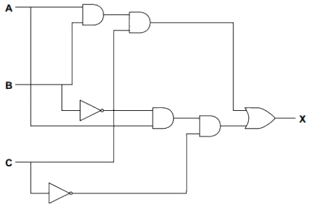
Example
A | B | C | X |
|---|---|---|---|
0 | 0 | 0 | 0 |
0 | 0 | 1 | 0 |
0 | 1 | 0 | 0 |
0 | 1 | 1 | 0 |
|
|
|
|
1 | 0 | 1 | 0 |
1 | 1 | 0 | 0 |
|
|
|
|
Look at the truth table and find the rows where X = 1
This happens when:
A = 1, B = 0, C = 0
A = 1, B = 1, C = 1
Build a logic branch:
A = 1, B = 0, C = 0
Use a NOT gate on B
Use a NOT gate on C
AND A, NOT B, and NOT C together
This gives output = 1 for that row
A = 1, B = 1, C = 1
Just AND A, B, and C together
Combine the branches
Use an OR gate to combine the two outputs
This way, X = 1 if either input combination happens
Determine the gates needed:
NOT gates:
NOT B
NOT C
AND gates:
A AND NOT B → first AND
that result AND NOT C → second AND
A AND B → third AND
that result AND C → fourth AND
OR gate:
Combines the outputs of the second and fourth AND gates
Construct the logic expression
Final logic:
(A AND NOT B AND NOT C) OR (A AND B AND C)
Create the logic circuit

Unlock more, it's free!
Join the 100,000+ Students that ❤️ Save My Exams
the (exam) results speak for themselves:

Was this revision note helpful?