Free Body Diagrams (AQA GCSE Combined Science: Trilogy): Revision Note
Exam code: 8464

Written by: Katie M
Updated on
Examples of Forces
Higher Tier Only
Tension
Tension is:
The force experienced by a cable, rope, or string when pulled, hung, rotated or supported
This is normally labelled as T on free body diagrams

Tension always acts away from the mass
Normal Contact Force
The normal contact force is:
The force arising when an object rests against another object acting at a 90° angle to the plane of contact
It is sometimes also referred to as the reaction force
This is normally labelled as N or R on free body diagrams
This force arises from Newton's Third Law

Normal contact force always acts perpendicular to the surface
Upthrust
Upthrust is:
The upward buoyancy force acting on an object when it is in a fluid
Upthrust can occur in liquids and gases

Upthrust always acts upwards
Friction
Friction is:
The force that arises when two surfaces are in contact with each other
Friction always opposes the motion
This is normally labelled as F or Fr on free body diagrams

Friction always acts at the point where the objects are in contact, and in the opposite direction to the direction of motion
Free Body Diagrams
Higher Tier Only
Free body diagrams are useful for modelling the forces that are acting on an object
Each force is represented as a vector arrow, where each arrow:
Is scaled to the magnitude of the force it represents
Points in the direction that the force acts
Is labelled with the name of the force it represents
Free body diagrams can be used:
To identify which forces act in which plane
To resolve the net force in a particular direction

Free body diagrams can be used to show the various forces acting on objects
Worked Example
Draw free-body diagrams for the following scenarios:
a) A picture frame hanging from a nail
b) A box sliding down a slope
c) A man fishing in a stationary boat
d) A car accelerating along a road
Answer:
Part (a)

The size of the arrows should be such that the 3 forces would make a closed triangle as they are balanced
Part (b)

There are three forces acting on the box
The normal contact force, R, acts perpendicular to the slope
Friction, F, acts parallel to the slope and in the opposite direction to the direction of motion
Weight, W, acts down towards the Earth
Part (c)
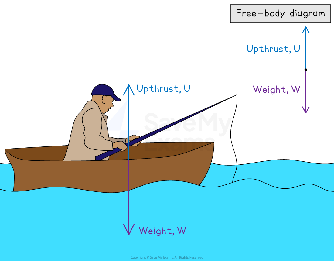
As the boat is not moving, the size of both arrows must be the same
Part (d)

As the car is accelerating, the size of the thrust must be larger than the size of the friction force
As in part (c), the upwards and downwards forces must be equal
Worked Example
Draw a free-body diagram of a toy sail boat with weight 30N floating in water that is being pulled to the right by an applied force of 35N.
Answer:
Step 1: Draw the object in a simplified diagram
Step 2: Identify all of the forces acting upon the object in the question, including any forces that may be implied
Weight: 30N down
Upthrust from the water (since the object is floating): 30N up
Applied force: 35N to the right
Step 3: Draw in all of the force vectors (arrows), making sure the arrows start at the object and are directed away

Determine the resultant in each direction separately
Vertical:
Weight (30 N down)
Upthrust (30 N up)
Fv = 30 + (−30) = 0 N
The vertical forces are balanced
So, there is no resultant vertical force
Horizontal:
The applied force (35 N right) acts alone
Fh = 35 N to the right
The resultant force is directed to the right

Unlock more, it's free!
Join the 100,000+ Students that ❤️ Save My Exams
the (exam) results speak for themselves:

Was this revision note helpful?