11 mark
Two resistors are connected in series to a 12 V battery.
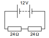
What is the current in one of the resistors?
0.25 A
0.50 A
2.0 A
4.0 A
Was this exam question helpful?
Exam code: 0653
Two resistors are connected in series to a 12 V battery.
What is the current in one of the resistors?
0.25 A
0.50 A
2.0 A
4.0 A
Was this exam question helpful?
The diagram shows a battery that is connected to three LEDs, P, Q and R.
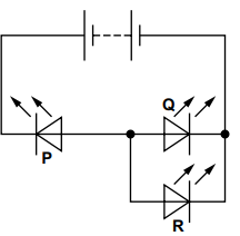
Which of the LEDs are lit?
P only
P and Q only
Q and R only
none of them
Was this exam question helpful?
The diagram shows a 12 V battery connected to an ammeter and two resistors.
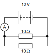
What is the reading on the ammeter?
0.60 A
1.2 A
2.4 A
60 A
Was this exam question helpful?
A teacher wants to connect an electric heater to the mains supply.
The safety label on the heater states that the heater is double-insulated.
What does the teacher know from reading this label?
The outer casing of the heater does not need to be earthed.
The outer casing of the heater must be earthed.
The heater needs two fuses.
The heater needs two trip switches.
Was this exam question helpful?
Fig. 7.1 shows an electric heater connected in a circuit.
Fig. 7.1
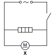
(i) State the name of component X.
[1]
(ii) The current in component X is 0.5 A.
The current in the heater is 8.3 A.
Circle the value of the current from the source.
0.5 A7.8 A8.3 A8.8 A
[1]
(iii) The electric heater uses 2.0 kW of electrical power.
Electrical energy costs $0.15 per kWh.
Calculate the cost of using the heater for 5.5 hours.
[2]
Was this exam question helpful?
Fig. 9.1 shows a circuit used in a toy car.
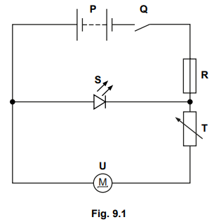
Fig. 9.1
(i) The resistance of component T is . The resistance of component U is .
Calculate the combined resistance of components T and U.
[1]
(ii) The current in component R is 2.7 A. The current in component T is 2.5 A.
Determine the current in component S and component U.
[2]
(iii) State the name of component S.
[1]
Was this exam question helpful?