Synoptic Exam Questions (Paper 1 & 2) (AQA A Level Physics): Exam Questions

Exam code: 7408

4 hours20 questions
1a
1 mark

Figure 1 shows a single particle of an ideal gas, of mass m, inside a rectangular box. The particle travels with velocity ux in the x-direction, moving backwards and forwards between the two shaded faces of the box and colliding with each in turn.

Figure 1

A rectangular box drawn in three dimensions, with x, y and z axes drawn from its bottom left corner. The two end faces at right angles to the x-axis are shaded grey. The length of the box between the shaded faces is labelled Lx, its depth is labelled Ly and its height is labelled Lz. A particle, shown as a dot inside the box, has an arrow labelled ux pointing in the positive x-direction, towards the right-hand shaded face

The box has dimensions Lx, Ly and Lz.

Deduce an expression, in terms of Lx and ux, for the time interval t between successive collisions of the particle with the same shaded face.

1b
1 mark

Explain why the change in momentum of the particle during one collision with a shaded face is −2mux.

1c
3 marks

The box contains N particles of the ideal gas, which have a mean square speed of ux2¯ in the x-direction.

Show that the average force F exerted by the particles on one of the shaded faces is given by F=Nmux2¯Lx, stating one assumption you make.

2a
2 marks

The core of a thermal nuclear reactor contains a number of components that are exposed to moving neutrons. 

State what happens to a neutron that is incident on: 

  • the moderator

  • a control rod.

2b
3 marks

A slow-moving neutron collides with a nucleus of an atom of the fuel which induces nuclear fission. 

Describe what happens in the process of induced fission.

2c
3 marks

A student sets up the arrangement, shown in Figure 8, to demonstrate the principle of moderation in a nuclear reactor.

Figure 8

8-4-s-q--q3c-medium-aqa-a-level-physics

A golf ball of mass m is initially hanging vertically and just touching a hockey ball of mass 3m. The golf ball is pulled up to the side and released. After the collision, the balls move in opposite directions with equal speeds.

Explain, with numerical detail, how this arrangement demonstrates the moderation process in a reactor.

2d
2 marks

A thermal nuclear reactor produces radioactive waste.

State the main source of the most dangerous waste and describe one problem faced in dealing with the waste.

3a
2 marks

Thin films of carbon are sometimes used in electronic systems. 

Typical dimensions of such a film are shown in Figure 7.

Figure 7

WYi3oQ4L_5-2-s-q--q2a-hard-aqa-a-level-physics

Calculate the current which passes through the carbon film shown in Figure 7 for an applied voltage of 2.5 mV. 

The resistivity of carbon = 4.0 × 10⁻⁵ Ω m

3b
3 marks

The applied voltage is kept constant, but the current is now directed through the carbon film as shown in Figure 8.

Figure 8

5-2-s-q--q2b-hard-aqa-a-level-physics

Show that the current is approximately 6 magnitudes larger when directed through the carbon film, as shown in Figure 8.

3c
4 marks

A tensile force is applied to the carbon film in Figure 8 in a plane that is normal to the current. 

Without performing any calculations, state and explain how the resistance of the carbon film changes as a result of the applied tensile force, stating one assumption you make.

4a
2 marks

The International Space Station (ISS) orbits travels around the Earth once every 93 minutes. 

Calculate the angular speed of the ISS.

4b
3 marks

Calculate the distance of the ISS above the Earth’s surface.

4c
3 marks

The Soyuz is a Russian spacecraft that carries astronauts to and from the international space station (ISS). The ISS has a mass of approximately 4.2 × 10⁵ kg. 

Calculate the change in kinetic energy of a Soyuz travelling from the Earth’s surface to the ISS.

4d
2 marks

Without performing any further calculations, explain how the change in kinetic energy relates to the change of the potential energy when the Soyuz travels from the Earth’s surface to the ISS. 

5a
1 mark

Cyclotrons are used to accelerate particles, such as protons, for a number of applications. 

A cyclotron has two D-shaped regions called ‘dees’ where the magnetic flux density is constant. The dees are separated by a small gap. An alternating electric field between the dees accelerates charged particles. The magnetic field causes the charged particles to follow a circular path. 

Figure 5 shows the path followed by a proton that starts from O.

 Figure 5

screenshot-2023-10-02-094308

State the direction the magnetic field acts over the dees in Figure 5.

5b
2 marks

Explain why it is not possible for the magnetic field to alter the speed of a proton while it is in one of the dees.

5c
3 marks

Show that the time taken by a proton to travel around one semi-circular path is independent of the radius of the path.

5d
2 marks

The maximum radius of the path followed by the proton is 0.46 m and the magnetic flux density of the uniform field is 0.88 T. 

Calculate the maximum speed of a proton when it leaves the cyclotron. 

Ignore any relativistic effects.

5e
2 marks

The protons leave the cyclotron when the radius of their path is equal to the outer radius of the dees. 

Determine the radius required for the cyclotron to produce protons with a maximum kinetic energy of 25 MeV. 

Ignore any relativistic effects.

6a
2 marks

A student investigates the refraction of light using a semicircular glass block. The refractive index of the glass is 1.52.

State the two conditions required for total internal reflection to occur at a boundary.

6b
2 marks

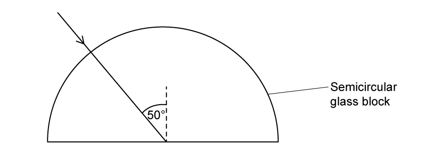
A ray of light strikes the flat surface of the block at an angle of 50° to the normal, as shown in Figure 2.

Figure 2

A semicircular glass block with an arrow indicating a light ray hitting the straight edge at a 50-degree angle.

Complete, on Figure 2, the path of the ray of light.

Support your answer with a suitable calculation.

6c
2 marks

The flat surface of the glass block is now placed in contact with water.

Explain how the student could use the glass block to measure the refractive index of water.

6d
3 marks

The student then uses a diffraction grating to analyse the light from a sodium lamp. The sodium lamp emits two closely spaced wavelengths known as the sodium doublet:

λ1=589.0 nm    λ2=589.6 nm

The diffraction grating has 600 lines per mm.

Calculate the angle of diffraction for the second-order maximum of λ1.

6e
3 marks

The student wants to resolve the sodium doublet and is considering two options:

  • Option 1: observe the second-order spectrum (n=2) using the original 600 lines per mm grating

  • Option 2: observe the first-order spectrum (n=1) using a different grating with 1200 lines per mm

Discuss which option the student should choose.

7a
2 marks

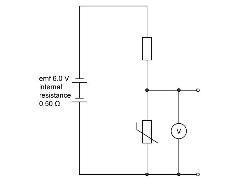
Figure 4 shows part of a circuit used to detect temperature changes.

A fixed resistor of resistance 2.5 Ω is connected in series with a thermistor of resistance 12 Ω at room temperature. The battery has an emf of 6.0 V and an internal resistance of 0.50 Ω.

Figure 4

Circuit diagram showing a battery of emf 6.0 volts and internal resistance 0.50 ohms connected in series with a fixed resistor and a thermistor. A voltmeter is connected in parallel across the thermistor.

Calculate the current in the circuit.

7b
2 marks

Calculate the expected reading on the voltmeter.

7c
2 marks

The actual voltmeter reading is 4.6 V.

Suggest one reason for the difference between the expected and actual readings.

7d
3 marks

The fixed resistor is made from a wire of length 0.80 m and diameter 0.28 mm.

Calculate the resistivity of the wire.

7e
3 marks

The thermistor is heated so that its resistance decreases to 3.0 Ω. A warning LED is to be connected in parallel with either the fixed resistor or the thermistor. The LED illuminates when the potential difference across it exceeds 2.0 V.

Determine which component the LED should be connected across so that it acts as a high-temperature warning. Support your answer with calculations.

8a
2 marks

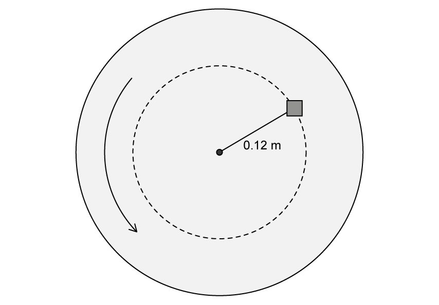
A turntable rotates at a constant angular speed. A small block of mass 0.050 kg is placed on the turntable at a distance of 0.12 m from the centre, as shown in Figure 6.

Figure 6

Top-down view of a circular turntable with a small block at distance 0.12 metres from the centre. Arrow showing direction of rotation (anticlockwise)

The block is on the verge of sliding when the turntable completes one revolution every 0.85 s.

Calculate the angular speed of the turntable.

8b
2 marks

Show that the frictional force acting on the block is approximately 0.3 N.

8c
2 marks

The block is now moved to a distance of 0.20 m from the centre. The turntable continues to rotate at the same angular speed. The maximum frictional force between the block and the turntable surface does not change.

Determine whether the block will slide at this new position.

8d
1 mark

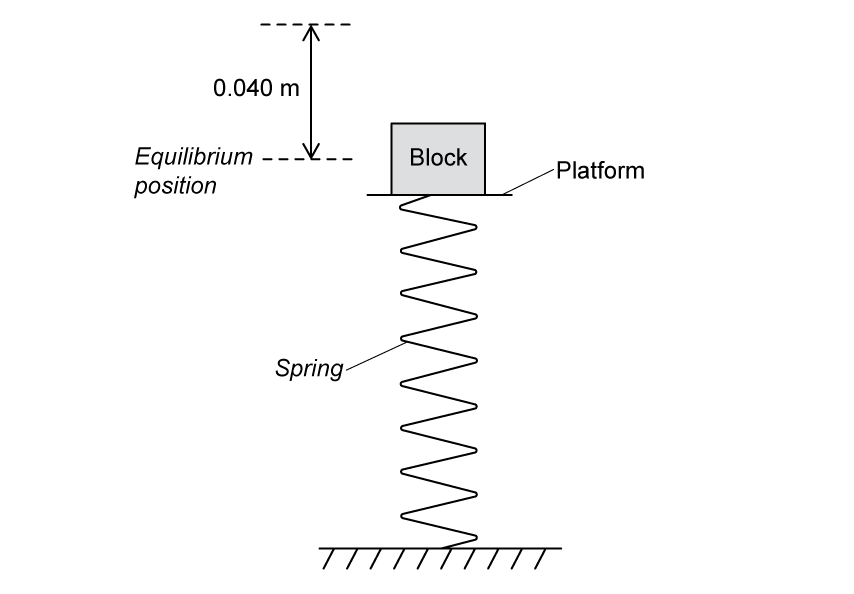
The block is placed on a horizontal platform that is attached to a vertical spring, as shown in Figure 7. The platform oscillates vertically with simple harmonic motion. At a frequency of 2.5 Hz, the mass just loses contact with the platform at the highest point of the oscillation when the amplitude is 0.040 m.

Figure 7

Side view of a vertical spring attached to a horizontal platform. A small block sits on top of the platform. The distance between the equilibrium position and the highest point of oscillation is 0.040 metres.

Suggest the condition required for the mass to lose contact with the platform at the highest point.

8e
2 marks

Calculate the maximum amplitude at a frequency of 4.0 Hz for which the block remains in contact with the platform throughout the oscillation.

9a
1 mark

State what is meant by the internal energy of an ideal gas.

9b
2 marks

A sealed glass flask of volume 0.020 m3 contains air at 27°C. The pressure of air in the flask is 1.5×10⁵ Pa.

Calculate the number of molecules of air in the flask.

9c
3 marks

Explain, using the kinetic theory model, why the pressure of an ideal gas increases when it is heated at constant volume.

9d
2 marks

The temperature of the air is increased from 27°C to 127°C.

Calculate the change in the mean kinetic energy of a molecule of air in the flask.

9e
3 marks

When an ideal gas is heated at constant volume, all of the energy supplied by heating is used to increase the mean kinetic energy of the particles.

When air is heated at constant volume, its specific heat capacity is 720 J kg−1 K−1.

Deduce whether air behaves as an ideal gas when heated at constant volume.

molar mass of air = 2.9×10⁻² kg mol−1

10a
4 marks

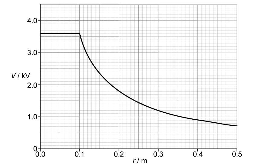
An isolated solid conducting sphere of radius 0.10 m is positively charged.

Figure 1 shows how the electric potential V varies with distance r from the centre of the sphere.

Figure 1

Graph of electric potential V in kilovolts against distance r in metres from the centre of a charged conducting sphere. Vertical axis: V / kV, from 0 to 4 kV, with major gridlines every 1 kV and minor gridlines every 0.5 kV. Horizontal axis: r / m, from 0 to 0.50 m, with major gridlines every 0.10 m and minor gridlines every 0.05 m. The curve begins at  (0.10,3.60) and decreases following an inverse relation between V and r: key points at (0.15,2.40), (0.20,1.80), (0.25,1.44), (0.30,1.20), (0.40,0.90), (0.50,0.72). Smooth continuous curve (no data points marked), clearly non-linear and concave upward. A straight horizontal line is plotted for r<0.10 m. Both axes labelled with quantity and unit.

Determine the magnitude of the electric field strength at a distance of 0.20 m from the centre of the sphere.

State an appropriate SI unit for your answer.

10b
3 marks

The sphere acts as a capacitor because it stores charge at an electric potential.

Show that the capacitance of the sphere is approximately 1×10⁻¹¹ F.

10c
3 marks

The charged sphere momentarily touches an identical uncharged conducting sphere. The two spheres are then separated.

Explain why the total energy stored by the two spheres after separation is less than the energy stored by the single sphere before contact.

11a
2 marks

Two stable isotopes of helium are He24 and He23.

An atom of He24 is produced in a rock that contains uranium. It is produced following the radioactive decay of a U92238 atom. The decay also creates an atom of thorium (Th).

Write an equation for the decay of U92238.

U92238→ ....................................................................

11b
2 marks

A He23 nucleus can be produced by the decay of a tritium nucleus H13.

State and explain which exchange particle is responsible for this decay.

11c
2 marks

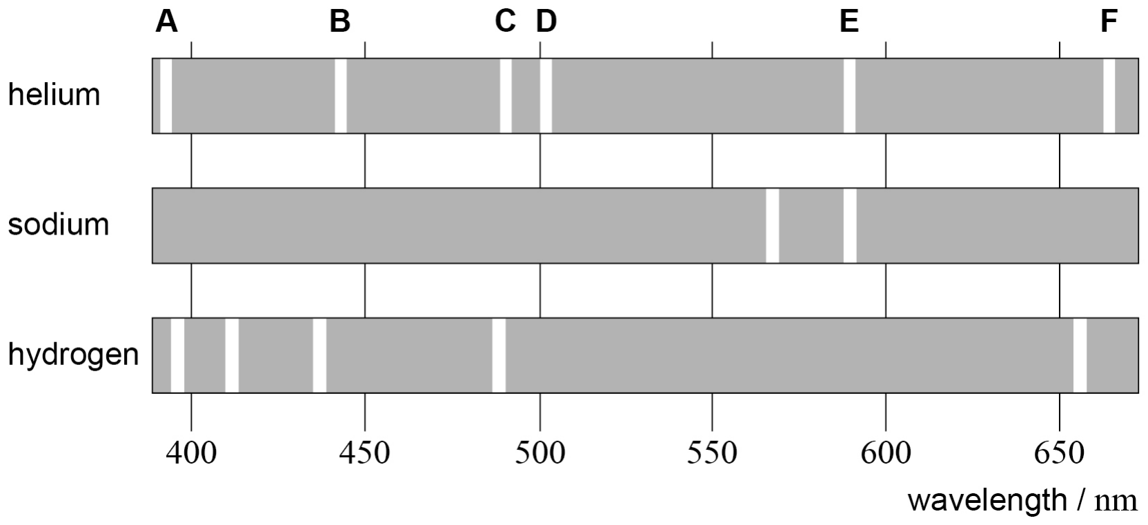
Helium was discovered by analysing the light in the absorption spectrum of the Sun.

Figure 1 shows the positions of the brightest lines, labelled A to F, in the emission spectrum of helium. The brightest lines in the emission spectra of sodium and hydrogen are also shown.

Figure 1

Emission lines of helium (six, labelled A to F from the left), sodium (two) and hydrogen (five) above a wavelength / nm scale numbered every 50 from 400 to 650, with no smaller divisions. Vertical guide lines rise from each numbered value.

Before helium was identified, some scientists suggested that the lines of the helium spectrum seen in the absorption spectrum of the Sun were due to the presence of sodium and hydrogen.

Discuss, with reference to the lines A to F in Figure 1, the evidence for and against this suggestion.

11d
3 marks

Calculate, in eV, the change in energy level responsible for the spectral line labelled E in Figure 1.

change in energy level = .................................... eV

11e
3 marks

Explain, with reference to the processes within an atom, the difference between an emission spectrum and an absorption spectrum.

12a
3 marks

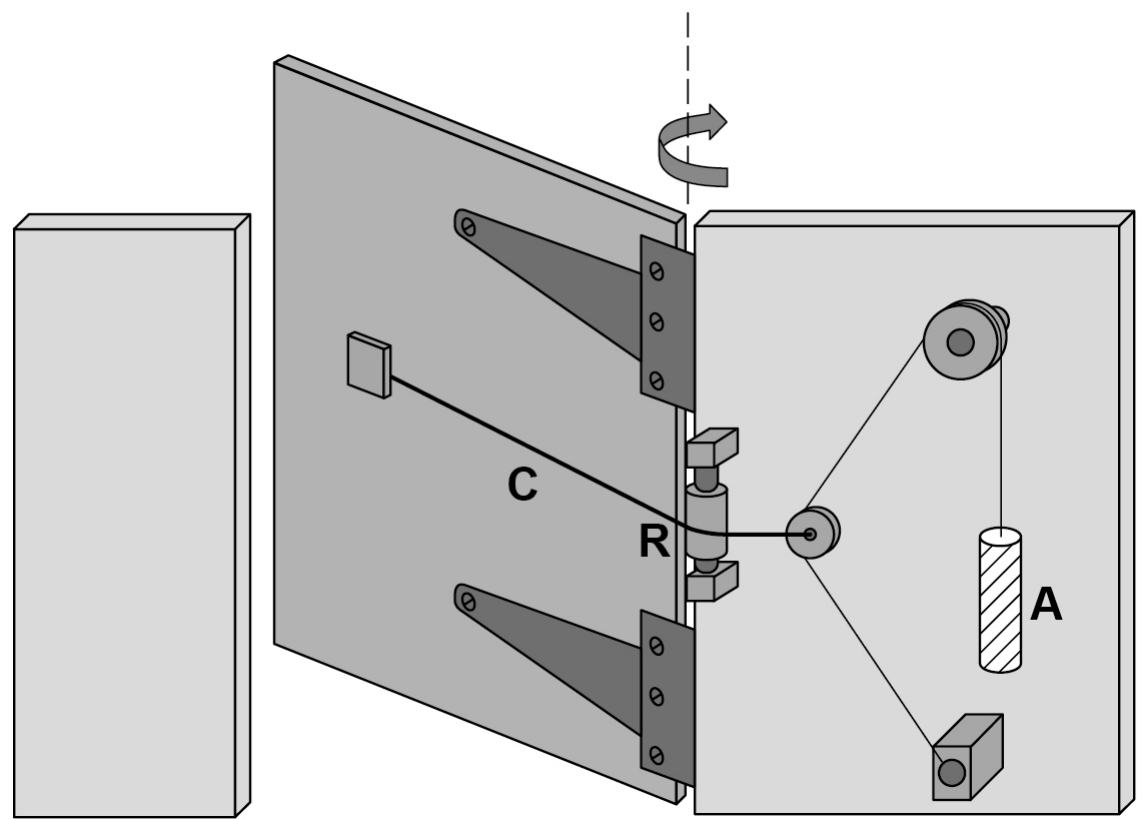
Figure 3 shows a garden gate with a pulley system designed to close the gate.

Figure 3

A garden gate hinged to a post. Horizontal cable C runs from the gate past pulley R at the hinge to a small pulley on the post. From there, a rope runs up over a larger pulley and down to a hanging cylinder A, and another runs down to an anchor block.

The pulley system raises weight A when the gate is opened. When the gate is released, A falls. The horizontal cable C passes over pulley R. The tension in cable C causes the gate to close.

Weight A is a solid cylinder with the following properties:

diameter = 4.8×10⁻² m
length = 0.23 m
weight = 35 N

Table 2 gives the density of three available materials.

Table 2

Material

Density / kg m-3

concrete

2.4×10³

iron

7.8×10³

brass

8.6×10³

Deduce which one of the three materials is used for A.

12b
2 marks

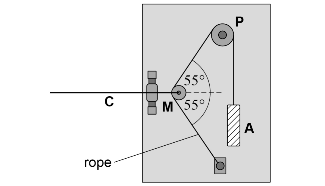
Figure 4 shows the pulley arrangement when the gate is closed.

Figure 4

Front view: cable C pulls horizontally on moveable pulley M. A rope from an anchor block passes round M and up over fixed pulley P to hanging cylinder A. Both rope sections at M make 55° with the line of cable C, one above and one below.

Pulleys P and M are frictionless so that the tension in the rope attached to A is equal to the weight of A.

A weighs 35 N and the weight of moveable pulley M is negligible.

Calculate the tension in the horizontal cable C when the gate is closed.

tension = .................... N

12c
2 marks

Pulley M is pulled to the left as the gate is opened.

Explain why this increases the tension in the horizontal cable C.

12d
2 marks

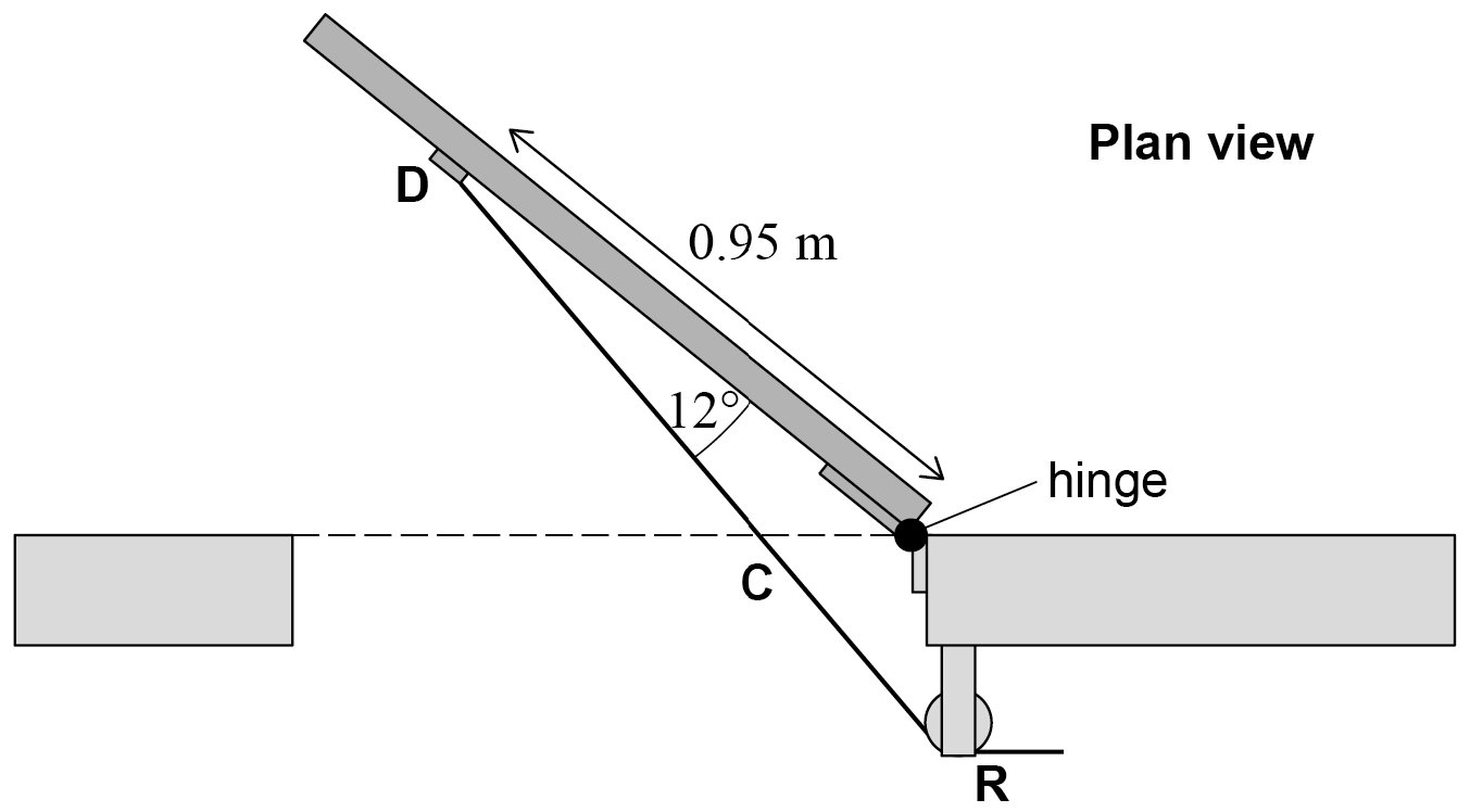
Figure 5 shows a plan view with the gate open. The horizontal cable C passes over pulley R and is attached to the door at D.

The angle between the door and the horizontal cable C is 12°.

The horizontal distance between the hinge and D is 0.95 m.

Figure 5

Plan view of the open gate. Point D is 0.95 m along the gate from the hinge. Cable C runs from D to pulley R beside the hinge, at 12° to the gate.

The tension in the horizontal cable C is now 41 N.

Calculate the moment of the tension about the hinge.

moment = .................... N m

12e
4 marks

The same system is attached to an identical gate with stiffer hinges. Now the system does not supply a sufficiently large moment to close the gate.

Discuss two independent changes to the design to increase the moment about the hinges due to horizontal cable C.

13a
3 marks

Cosmic rays are high-energy particles that come from space. Most of these particles are protons. There are other particles in cosmic rays, including atomic nuclei.

Table 1 gives the data for one particular nucleus X.

Table 1

Mass / kg

8.02 × 10⁻²⁶

Specific charge / C kg-1

4.39 × 10⁷

Kinetic energy / MeV

215

Determine the number of neutrons in nucleus X.

number of neutrons = ....................

13b
3 marks

Calculate the speed of X.

Ignore relativistic effects.

speed = .................... m s-1

13c
2 marks

A pion (π+) and a kaon (K+) are produced when cosmic rays interact with the upper atmosphere.

The π+ decays to produce a positron and an electron neutrino.

Show how the conservation laws apply to this decay.

13d
2 marks

The K+ decays to produce an anti-muon and a muon neutrino.

Explain how strangeness applies in this decay.

13e
2 marks

Write an equation for a K+ decay that involves only hadrons.

14a
2 marks

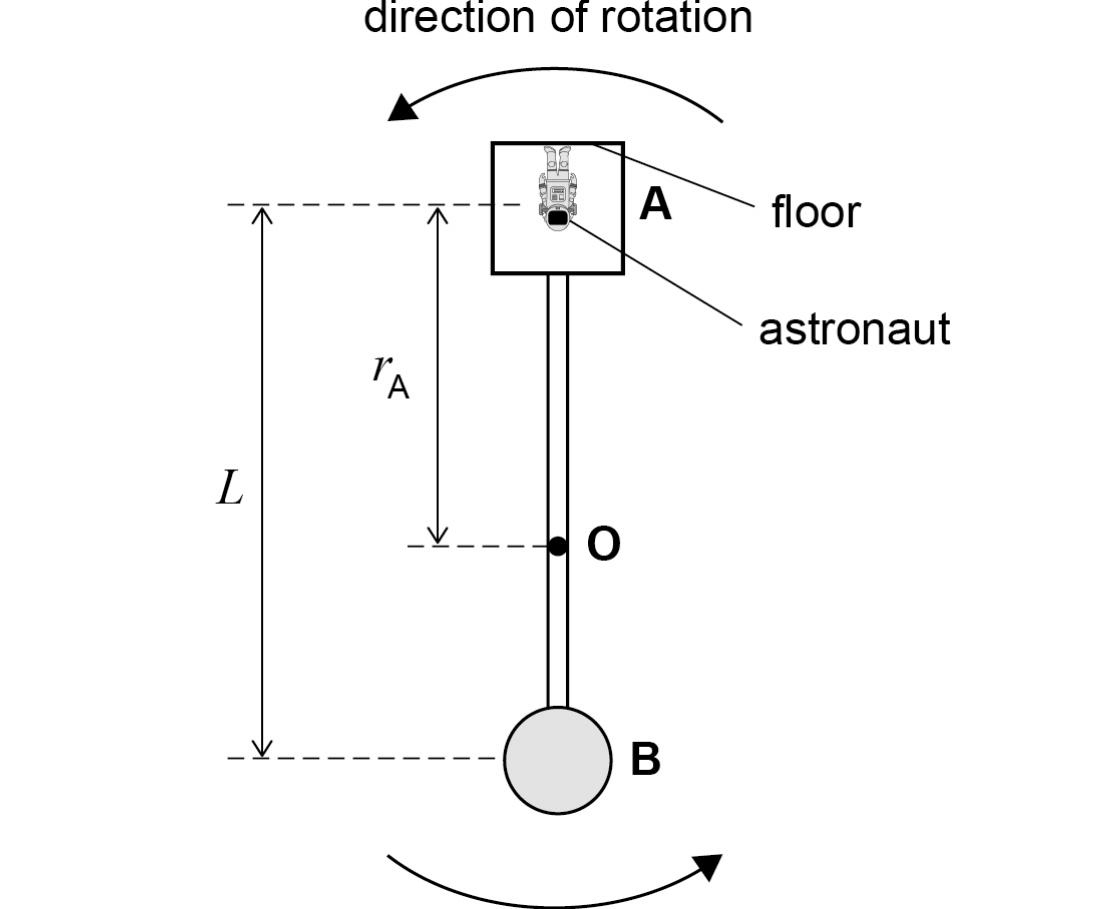
Figure 6 shows a rotating spacecraft that is proposed to carry astronauts to Mars.

Figure 6

A spacecraft rotating anticlockwise about point O: compartment A joined by a rod to sphere B. An astronaut in A stands on the wall furthest from O, head towards O. L is the distance between the centres of mass of A and B; rA is from the centre of mass of A to O.

The spacecraft consists of two parts A and B connected by a rigid cylindrical rod.

When the spacecraft is travelling, A and B rotate at a constant angular speed about their common centre of mass O.

L is the distance between the centre of mass of A and the centre of mass of B.

rA is the distance from O to the centre of mass of A.

As the spacecraft rotates, a force that imitates the effect of gravity acts on an astronaut who is in contact with the floor.

Explain why.

14b
2 marks

The forces exerted on A and B by the connecting rod have the same magnitude.

mA is the mass of A

mB is the mass of B

Show, by considering the centripetal forces acting on A and B, that rA is given by

rA=mBLmA+mB

14c
2 marks

In this spacecraft mA<mB.

Deduce whether the centre of mass of A or the centre of mass of B rotates with a greater linear speed.

14d
5 marks

The astronauts live in A and the cargo is stored in B.

When loaded,

mA=1.32×10⁶ kg

mB=3.30×10⁶ kg.

The spacecraft imitates the gravity of Mars where g=3.7 m s−2.

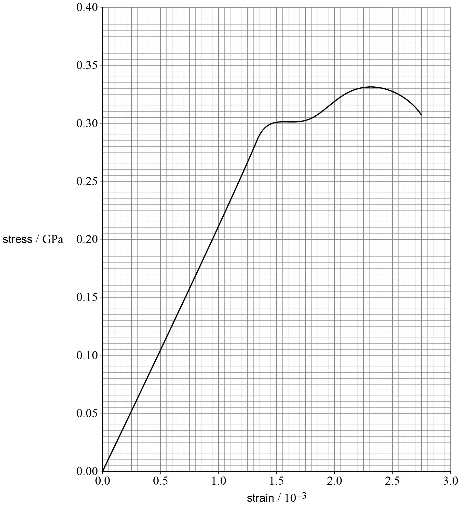
Figure 7 shows a stress–strain curve for the metal used for the rigid rod.

Figure 7

Stress–strain graph: stress / GPa from 0 to 0.40 against strain / 10⁻³ from 0 to 3.0. Small squares are 0.05 × 10⁻³ by 0.005 GPa. A straight line from the origin, a short near-flat section, then a gentle rise to a broad maximum and a fall to the end.

Suggest a suitable diameter for the rod.

Justify your answer.

diameter = .................... m

15a
3 marks

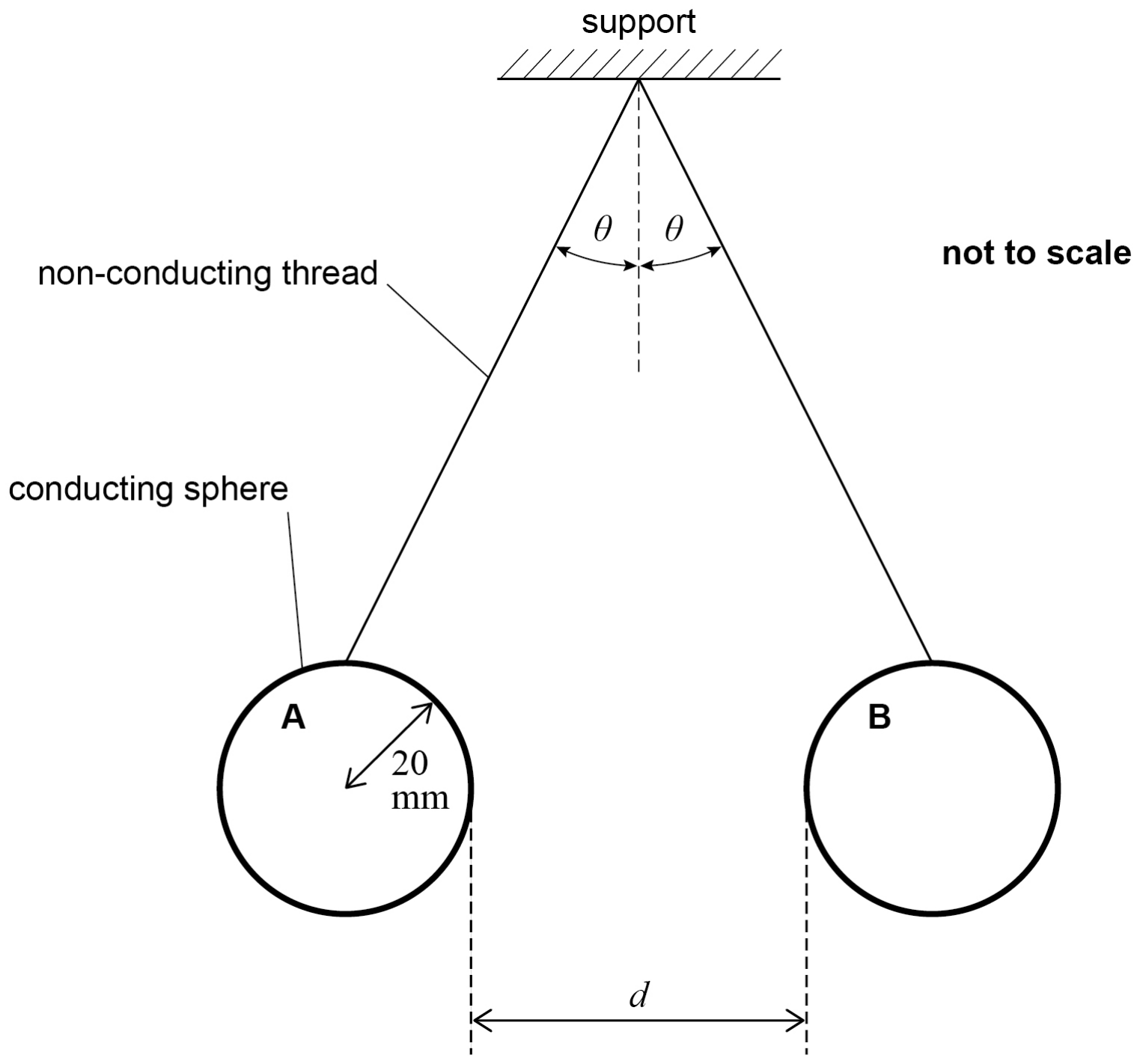
Figure 3 shows an arrangement used to investigate the repulsive forces between two identical charged conducting spheres.

The spheres are suspended by non-conducting thread.

Figure 3

Two identical conducting spheres, A and B, hang from one point on non-conducting threads, each at angle θ to the vertical. The radius of A is 20 mm. d is the gap between the spheres. Not to scale.

Each sphere has a mass of 3.2×10⁻³ kg and a radius of 20 mm.

The distance d is 40 mm.

The capacitance of a sphere of radius r is 4πϵ0r.

Each sphere is charged by connecting it briefly to the positive terminal of a high-voltage supply, the other terminal of which is at 0 V.

After this has been done the charge on each sphere is 52 nC.

Calculate the potential of one of the spheres.

potential = .................... V

15b
2 marks

The charged spheres in Figure 3 are at equilibrium.

Draw labelled arrows on Figure 3 to show the forces on sphere B.

15c
2 marks

Suggest a solution to one problem involved in the measurement of d in Figure 3.

15d
3 marks

Show that the magnitude of the electrostatic force on each sphere is about 4×10⁻³ N.

15e
2 marks

A student measures the angle θ when the apparatus in Figure 3 is at equilibrium.

The student records θ as 7°.

Discuss whether this measurement is consistent with the other data in this investigation.

15f
2 marks

The student says that the gravitational force between the two spheres has no significant effect on the angle at which the spheres are in equilibrium.

Deduce with a calculation whether this statement is valid.

16a
3 marks

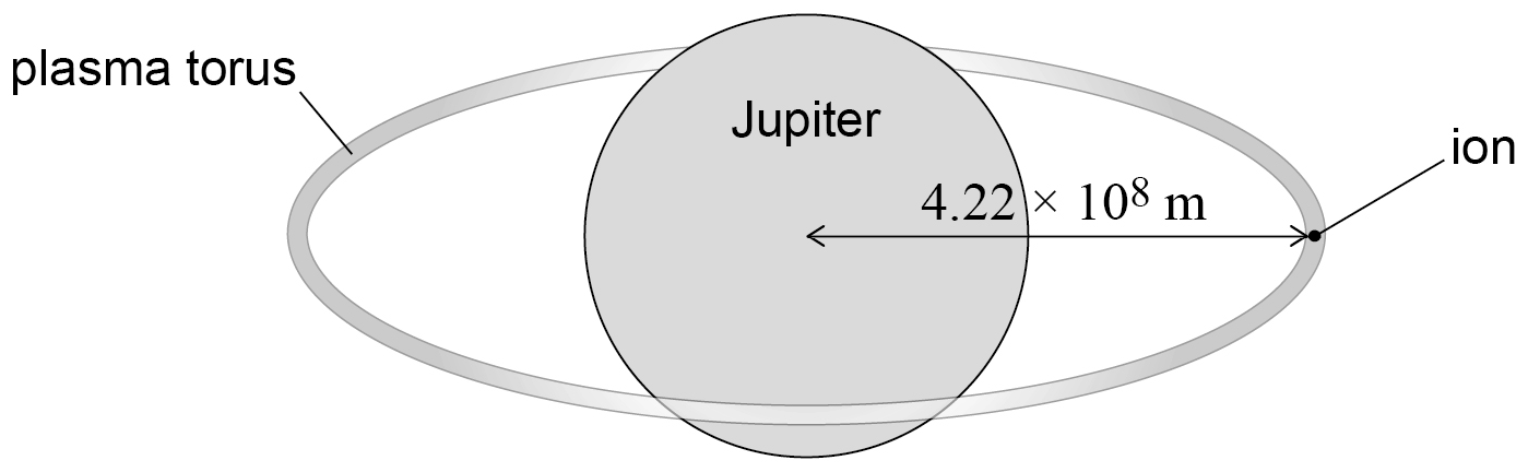
Ions orbit Jupiter in a ring called a plasma torus as shown in Figure 6.

This question is about applying gravitational, magnetic and electric fields to a particle in the plasma.

Figure 6

Jupiter with a ring-shaped plasma torus around it. An ion on the ring is 4.22 × 10⁸ m from the centre of Jupiter.

An ion travels in a circular path at a speed of 74.2 km s−1 and at a distance of 4.22×10⁸ m from the centre of Jupiter.

Student A suggests that the gravitational force acting on the ion due to Jupiter provides the centripetal acceleration of the ion.

Deduce whether this suggestion is correct.

mass of Jupiter = 1.90×1027 kg

16b
1 mark

Student B suggests that the magnetic field of Jupiter alone can cause the ion to move in the circular path.

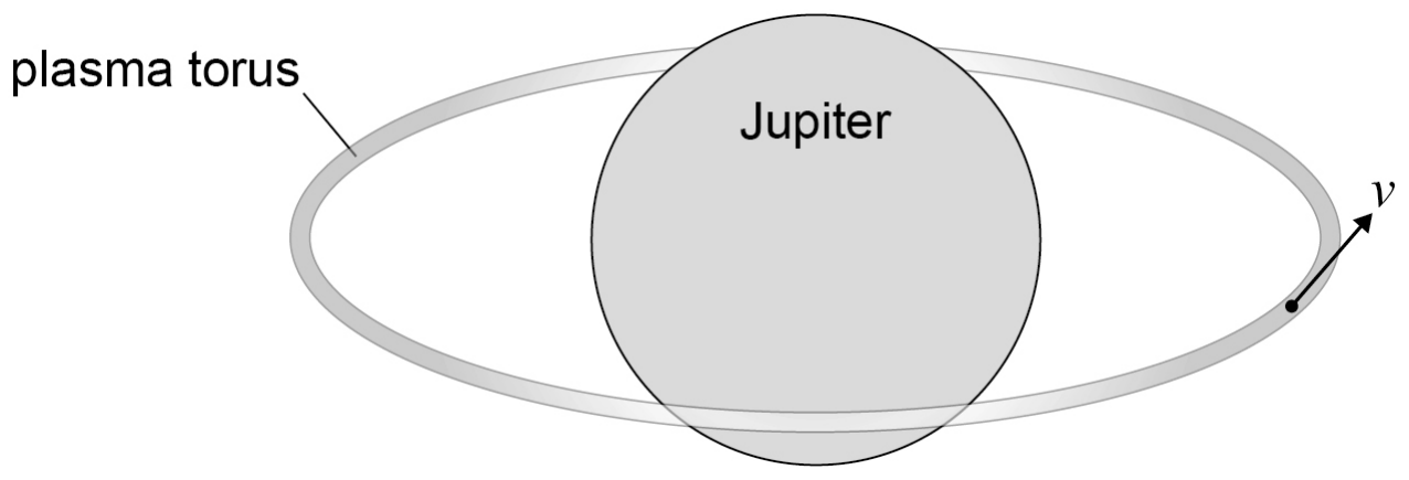
Figure 7 shows the direction of the velocity v of the ion in the plasma torus.

v is tangential to the plasma torus.

Figure 7

Jupiter and the plasma torus. An ion on the front of the ring has velocity v along the ring, moving round towards the back.

The ion has a positive charge.

Student B's suggestion requires a magnetic field to act at the position of the ion.

Draw an arrow on Figure 7 to show the direction of this magnetic field.

16c
3 marks

The ion has a charge of +3.20×10⁻¹⁹ C and a mass of 5.31×10⁻²⁶ kg.

The ion moves with a speed of 74.2 km s−1 in a circle of radius 4.22×10⁸ m.

Calculate the magnitude of the magnetic flux density required for this motion.

State, in fundamental (base) units, the unit for your answer.

Ignore any contribution from the gravitational field.

magnetic flux density = .................... unit = ....................

16d
3 marks

An electric field of strength 371 μV m−1 can also accelerate the ion.

Calculate the acceleration of the ion due to this electric field.

acceleration = .................... m s-2

16e
3 marks

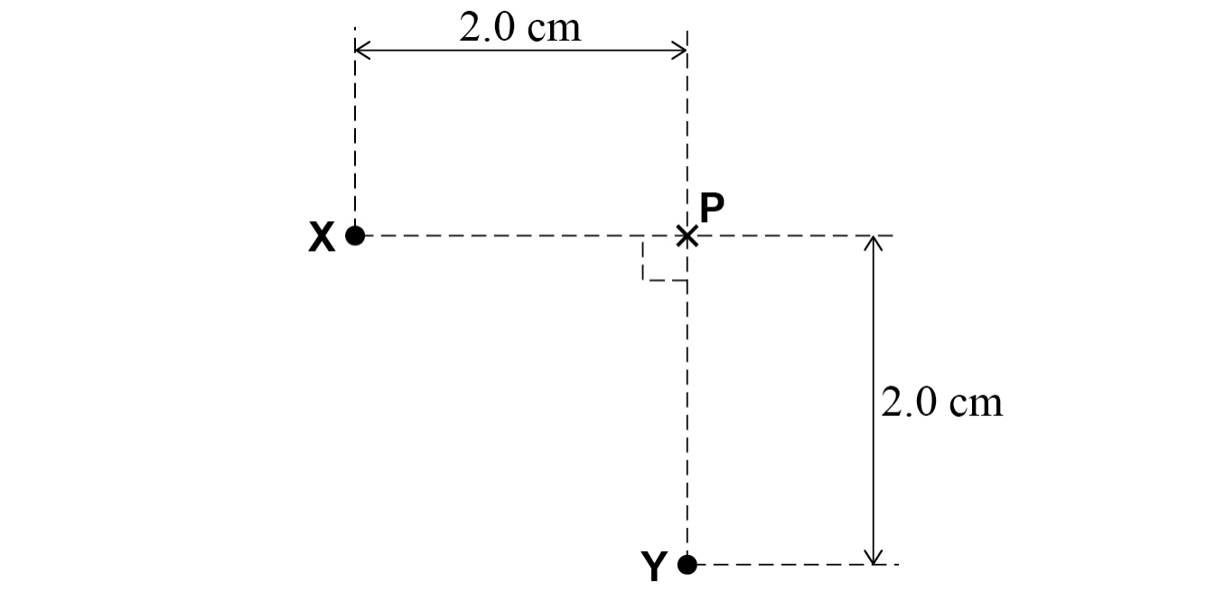
The plasma torus contains two ions X and Y as shown in Figure 8.

X has a charge of +2e.

Y has a charge of +1e.

Assume that each ion acts as a point charge.

Figure 8

Ions X and Y and point P. X is 2.0 cm to the left of P and Y is 2.0 cm directly below P, at right angles.

Calculate the magnitude of the resultant electric field strength at point P in Figure 8 due to the two ions.

resultant electric field strength = .................... V m-1

17a
2 marks

A radioisotope thermoelectric generator (RTG) uses radioactive decay to generate electrical energy.

A vehicle that is used to examine the surface of Mars includes an RTG that initially contains 3.23×1024 atoms of plutonium-238 (Pu94238).

Determine the initial mass of plutonium-238 in the RTG.

initial mass = .................... kg

17b
5 marks

The plutonium-238 undergoes alpha decay.

The energy released by this decay is converted into electrical energy with an efficiency of 4.58%.

The power provided by the RTG decreases over time as the plutonium-238 decays.

The vehicle requires a minimum electrical power of 29.6 W to operate.

Calculate the initial activity of the plutonium-238.

Go on to determine, in Earth years, the time for which the RTG can provide sufficient power for the vehicle to operate.

decay constant of plutonium-238 =2.51×10⁻¹⁰ s−1

energy of alpha particle emitted by plutonium-238 =8.94×10⁻¹³ J

initial activity = .................... Bq

time = .................... Earth years

17c
4 marks

The vehicle has a battery-powered laser that is used to vaporise small samples of ice.

On Mars, ice changes directly from solid to vapour at a temperature of 0 °C.

The ice does not form a liquid.

The energy required to vaporise 1.0 g of solid ice directly into water vapour is the same as the total energy required to melt 1.0 g of ice and then to vaporise the melted ice.

The laser produces an output power of 1.0 kW for a maximum time of 3.0 s before its battery needs to be recharged.

The laser heats the ice from an initial temperature of −25 °C to a temperature of 0.0 °C. The laser then transfers energy to vaporise the ice at 0.0 °C.

Determine whether the laser is able to vaporise 1.0 g of the ice that is initially at −25 °C before the battery needs to be recharged.

specific heat capacity of ice =2.1 kJ kg−1 K−1

specific latent heat of fusion of ice =334 kJ kg−1

specific latent heat of vaporisation =2500 kJ kg−1

18a
1 mark

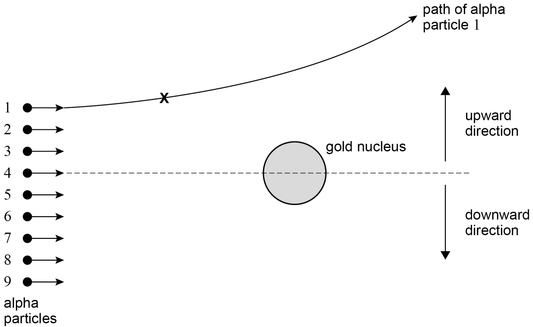
Figure 11 shows alpha particles all travelling in the same direction at the same speed.

The alpha particles are scattered by a gold (Au79197) nucleus.

The path of alpha particle 1 is shown.

Figure 11

Alpha particles 1 to 9, top to bottom, move right towards a gold nucleus level with particle 4. The path of particle 1 bends upwards as it passes above the nucleus. X is a point on this path before the nucleus. Arrows show the upward and downward directions.

State the fundamental force involved when alpha particle 1 is scattered by the nucleus in Figure 11.

18b
1 mark

Draw an arrow at position X on Figure 11 to show the direction of the rate of change in momentum of alpha particle 1

18c
2 marks

Suggest one of the alpha particles in Figure 11 which may be deflected downwards with a scattering angle of 90°

Justify your answer.

alpha particle number = ....................

18d
3 marks

Alpha particle 4 comes to rest at a distance of 5.5×10⁻¹⁴ m from the centre of the Au79197 nucleus.

Calculate the speed of alpha particle 4 when it is at a large distance from the nucleus.

Ignore relativistic effects.

mass of alpha particle =6.8×10⁻²⁷ kg

speed = .................... m s-1

18e
2 marks

The nuclear radius of Au79197 is 6.98×10⁻¹⁵ m.

Calculate the nuclear radius of Ag47107.

radius = .................... m

18f
1 mark

All nuclei have approximately the same density.

State one conclusion about the nucleons in a nucleus that can be deduced from this fact.

19a
1 mark

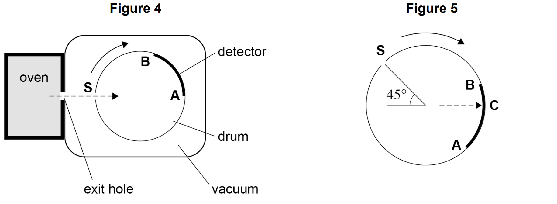
Figure 4 and Figure 5 show apparatus used in an experiment to confirm the distribution of atom speeds in a gas at a particular temperature.

Figure 4: atoms leave an oven, pass into a vacuum and through slit S in a drum rotating clockwise. A curved detector lines the far side of the drum from B (top) to A (level with S). Figure 5: the drum after rotating, with S at 45° above the horizontal on the left; C is on the detector directly opposite the centre, between B and A.

The oven contains an ideal gas kept at a constant temperature. Atoms of the gas emerge from the oven and some pass through the narrow slit S in a rapidly rotating drum. The drum is in a vacuum.

Explain why the drum must be in a vacuum.

19b
2 marks

One atom leaves the oven, enters the drum through S and travels in a straight line across the drum.

In the time taken for the atom to move from S to the detector AB, the drum rotates through 45°. The atom hits the detector at point C, as shown in Figure 5.

drum diameter = distance from S to A = 0.500 m

drum rotational speed = 120 revolutions per second

Show that the atom is moving at a speed of about 500 m s−1.

19c
3 marks

The speed of the atom in part (b) is equal to crms, the root mean square speed of the atoms of the gas in the oven.

The molar mass of the gas is 0.209 kg mol−1.

Calculate the temperature of the gas in the oven.

temperature = .................... K

19d
2 marks

The oven temperature is kept constant during the experiment but the pressure in the oven decreases as atoms leave through the exit hole.

Explain, using the kinetic theory, why the pressure decreases.

19e
1 mark

The pressure of gas in the oven is initially 5.0×10⁴ Pa.

The volume of the oven is 2.7×10⁻² m3.

During the experiment the pressure in the oven decreases to 4.5×10⁴ Pa.

Calculate, in mol, the amount of gas that has emerged from the oven.

amount of gas = .................... mol

19f
2 marks

Atoms enter the drum every time S passes the exit hole. The detector darkens at the point where an atom strikes it.

After a time, the detector is removed from the drum.

Figure 6 shows the appearance of the detector.

Figure 6

The detector removed from the drum, from B on the left to A on the right. It is darkest about a third of the way from B, fading on both sides to almost white near A.

A new detector is placed in the drum and the experiment is repeated with a new sample of the same gas at a higher temperature.

Describe and explain the appearance of this detector when the experiment is repeated.

20a
1 mark

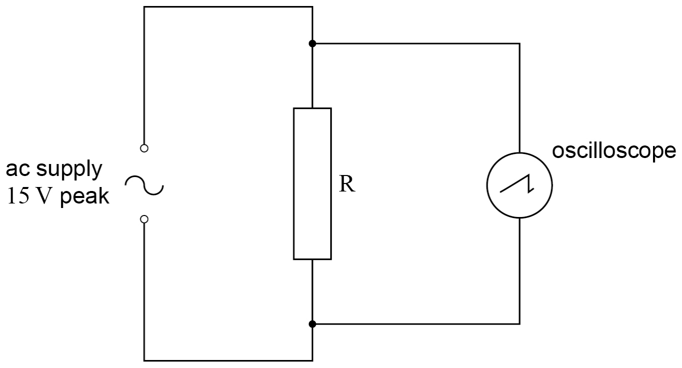
Figure 6 shows an oscilloscope connected across resistor R which is in series with an ac supply. The supply provides a sinusoidal output of peak voltage 15 V.

Figure 6

Circuit: an ac supply of 15 V peak in series with resistor R, with an oscilloscope connected across R.

Calculate the rms voltage of the supply.

rms voltage = .................... V

20b
1 mark

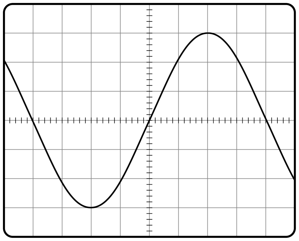
Figure 7 shows the trace of the waveform displayed on the oscilloscope.

Figure 7

Oscilloscope screen, 10 by 8 divisions, each split into five on the centre lines. A sine wave centred on the horizontal centre line, with peaks 3 divisions above and troughs 3 divisions below it.

Determine the y-voltage gain of the oscilloscope used for Figure 7.

y-voltage gain = .................... V div-1

20c
1 mark

A dc supply gives the same rate of energy dissipation in R as the ac supply in Figure 6.

Draw the trace of the output of the dc supply on Figure 7.

The oscilloscope settings remain the same.

20d
1 mark

The ac supply shown in Figure 6 is replaced with a square-wave generator operating between 0 and +15 V.

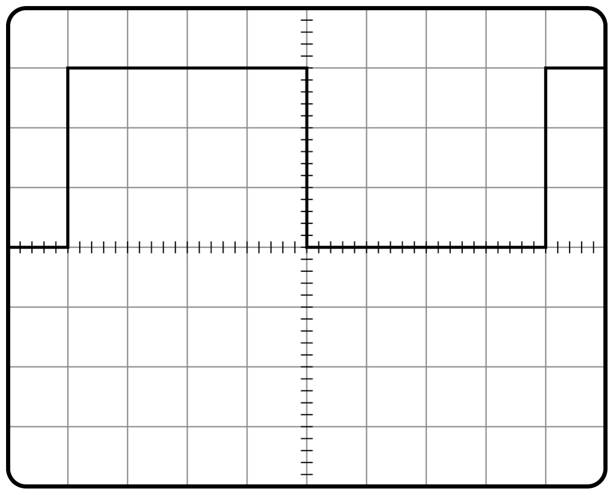
Figure 8 shows the trace of the new waveform displayed on the oscilloscope.

The time-base is set to 5.0×10⁻⁴ s div−1.

Figure 8

Oscilloscope screen, same grid as Figure 7. A square wave between the centre line and 3 divisions above it. It rises 1 division from the left edge, falls at 5 divisions and rises again at 9 divisions.

Calculate the frequency of the square waves.

frequency = .................... Hz

20e
3 marks

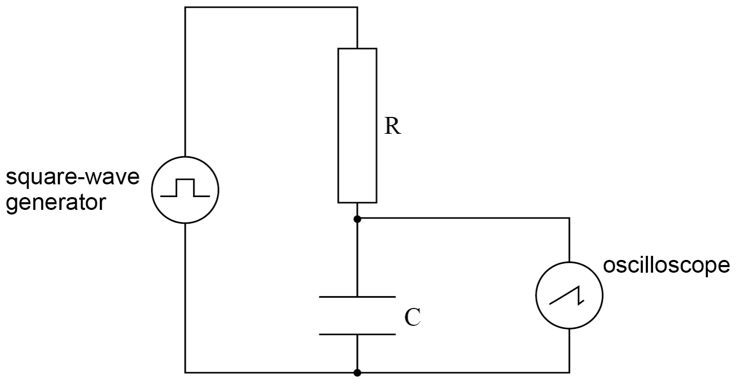
Figure 9 shows the arrangement with the square-wave generator connected to an RC circuit.

A capacitor C is placed in series with the resistor R.

The oscilloscope is connected across the capacitor C.

Figure 9

Circuit: a square-wave generator in series with resistor R and capacitor C, with an oscilloscope connected across C.

The capacitor charges and discharges.

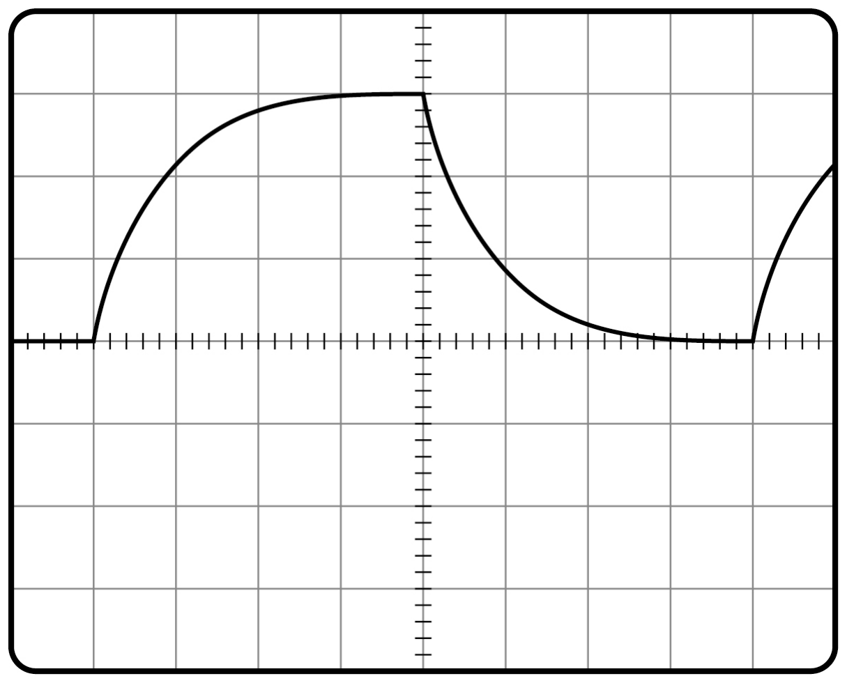
Figure 10 shows the trace of the waveform displayed on the oscilloscope.

The settings of the oscilloscope remain the same as in part (d).

Figure 10

Oscilloscope screen, same grid as Figure 7. From 1 division in from the left edge, the trace rises in a curve to a flat maximum 3 divisions above the centre line. At 5 divisions it starts to fall: it is about 1.5 divisions up half a division later and about 0.25 divisions up 2 divisions later. It rises again at 9 divisions.

Deduce the time constant for the RC circuit, explaining each step of your method.

time constant = .................... s

20f
2 marks

State and explain a change to one control setting on the oscilloscope that would reduce the uncertainty in the value of the time constant.