Magnetism & Electromagnetism (AQA GCSE Combined Science: Synergy: Physical Sciences): Exam Questions

Exam code: 8465

1 hour7 questions
1a
2 marks

A student investigated magnetic fields.

Figure 4 shows a cube-shaped magnet and a magnetic compass.

Figure 4
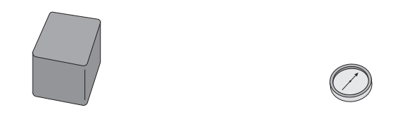
Diagram showing a cube-shaped magnet and a magnetic compass

Describe how the student could identify the poles of the magnet using the magnetic compass.

1b
1 mark

Figure 5 shows a wire with a current in it.

The arrow shows the direction of the current in the wire.

There is a magnetic field around the

Figure 5
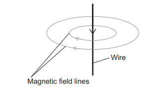
Diagram showing a wire with current flowing upwards, with concentric circular magnetic field lines around it (anticlockwise when viewed from above)

Figure 6 shows the wire when the current is in the opposite direction to Figure 5.

Figure 6
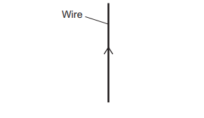
Diagram showing the wire only, for the student to draw the magnetic field

Complete Figure 6 to show the magnetic field around the wire.

1c
1 mark

Figure 7 shows an electromagnet made from a coil of wire wrapped around an iron core.

Figure 7
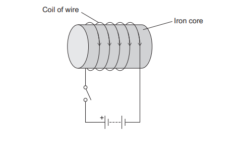
Diagram showing an electromagnet made from a coil of wire wrapped around an iron core, connected to a circuit with a switch

When the switch is closed, there is a magnetic field around the electromagnet.

Label on Figure 7:

  • the north pole N

  • the south pole S.

1d
2 marks

Explain why the acceleration of the paper clip changes as the paper clip moves towards the magnet.

2a
4 marks

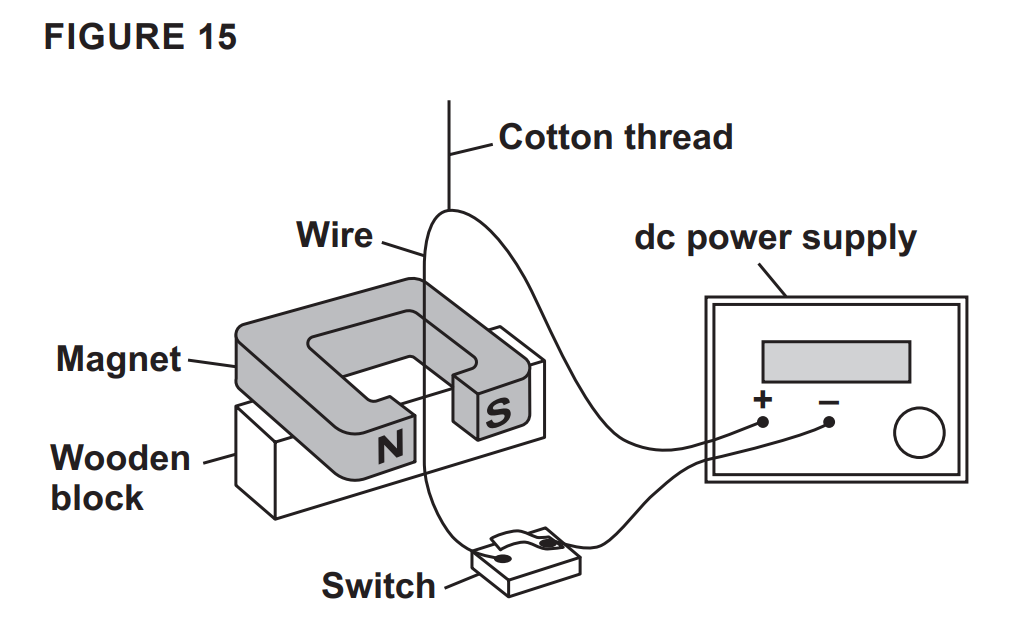
FIGURE 15 shows a wire held in place between the poles of a permanent magnet.

The wire is connected to an electrical circuit.

Diagram of a motor experiment: wire suspended on cotton thread between magnet poles on a wooden block, connected via switch to a DC power supply

When the switch is closed, the wire moves.

Explain why. [4 marks]

2b
Sme Calculator
6 marks

The length of wire in the magnetic field around the permanent magnet is 0.050 m.

The potential difference across the ends of the wire is 0.14 V.

The resistance of the wire is 0.040 Ω.

The magnetic flux density of the magnetic field around the permanent magnet is 22 mT.

Calculate the force on the wire.

Use the Physics Equations Sheet.

Force = ______________________ N

3a
1 mark

Permanent magnets have a magnetic field around them.

The Earth has a magnetic field.

Which part of the Earth’s internal structure creates the magnetic field?

Tick (✓) one box.

  • The crust

  • The mantle

  • The outer core

3b
1 mark

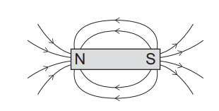
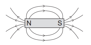
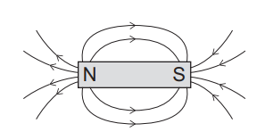
A magnetic compass contains a bar magnet.

Which diagram shows the magnetic field around a bar magnet?

Tick (✓) one box.

  • Diagram of a bar magnet labelled N and S with curved arrows showing magnetic field lines looping from the north pole to the south pole
  • Diagram of a bar magnet labelled N and S with curved field lines looping from the north pole around to the south pole, showing magnetic field direction
  • Diagram of a bar magnet labelled N and S with curved field lines showing magnetic field flowing from north pole to south pole outside the magnet
3c
1 mark

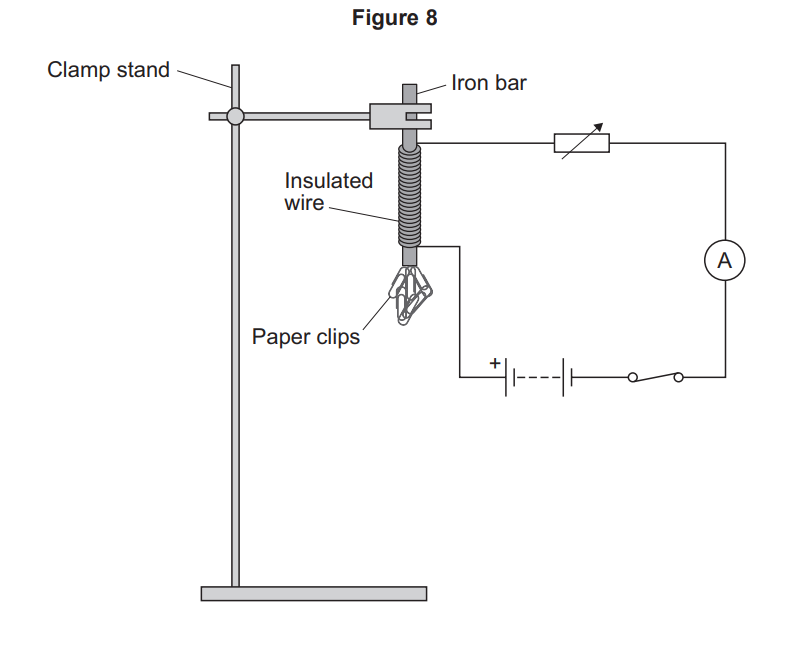
A student wrapped insulated wire around an iron bar to make an electromagnet.

Figure 8 shows the electromagnet held in a clamp and connected to a circuit.

Diagram of an electromagnet: iron bar in a clamp stand wrapped with insulated wire, attracting paper clips, in a circuit with cell, switch and ammeter.

When the switch was closed, the electromagnet attracted paper clips.

The student investigated how the number of turns of wire on the iron bar affected the strength of the electromagnet.

This is the method used:

  1. Wrap 20 turns of wire around the iron bar

  2. Hold the paper clips near the bottom of the electromagnet

  3. Close the switch

  4. Count the number of paper clips the electromagnet picks up

  5. Open the switch

  6. Repeat steps 1 to 5, but with more turns of wire around the iron bar

The student used the same value of current throughout the investigation.

What type of variable was the current?

Tick (✓) one box.

  • Control variable

  • Dependent variable

  • Independent variable

3d
1 mark

Table 4 shows the results. When there was no wire wrapped around the iron bar, no paper clips were picked up.

Table 4

Number of turns of wire

Number of paper clips picked up

Test 1

Test 2

Test 3

Mean

0

0

0

0

0

20

5

6

7

6

40

19

19

7

19

60

33

35

37

35

80

54

52

56

54

Draw a ring around the anomalous result in Table 4.

3e
1 mark

The student did not take another reading to replace the anomalous result.

What did the student do with the anomalous result when calculating the mean?

3f
1 mark

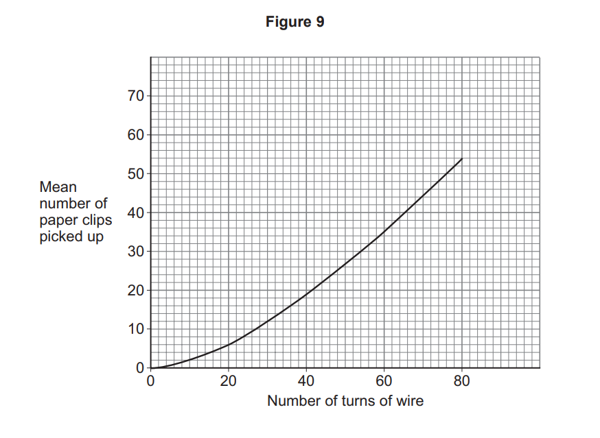
Figure 9 is a graph of the results.

Line graph titled Figure 9 showing mean paper clips picked up increasing non-linearly from 0 to about 55 as wire turns rise from 0 to about 85.

How many paper clips would be picked up when 70 turns of wire are wrapped around the iron bar?

Number of paper clips = _______________

3g
2 marks

The investigation was repeated using a larger current.

Draw a line on Figure 9 to show the expected results.

4a
1 mark

A student investigated the magnetic effect of an electric current.

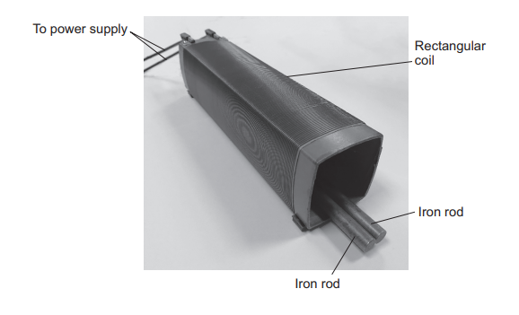
The student placed two iron rods inside a rectangular coil.

Figure 1 shows the equipment.

Figure 1

A rectangular coil of wire connected to a power supply, with two iron rods placed inside the coil parallel to its axis.

When the power supply is switched on there is a current in the rectangular coil.

Complete the sentence.

When there is a current in the rectangular coil, there is a magnetic field around the coil.

The magnetic field has a similar shape to the magnetic field around a __________________.

4b
2 marks

The two iron rods repel each other when there is a magnetic field around the coil.

Explain why.

4c
1 mark

The two iron rods are replaced with copper rods.

The two copper rods remain stationary when there is a magnetic field around the coil.

Give one reason why.

4d
1 mark

The student made an electromagnet by:

  • wrapping a coil of wire around an iron bar

  • connecting the coil of wire to a power supply.

The student investigated how the current in the electromagnet affected the strength of the electromagnet.

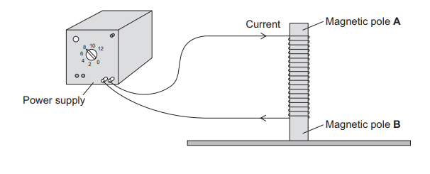
Figure 2 shows the electromagnet.

Figure 2

A coil of wire wrapped around an iron bar, with an ammeter (reading 4 A) in series with a power supply. The top of the iron bar is labelled Magnetic pole A and the bottom is labelled Magnetic pole B.

Identify magnetic poles A and B in Figure 2.

4e
1 mark

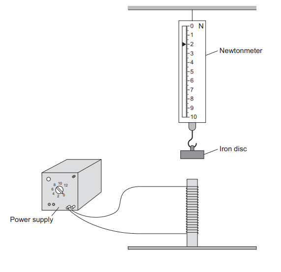
The student arranged a newtonmeter and an iron disc above the electromagnet.

Figure 3 shows the equipment.

Figure 3

A newtonmeter (0–10 N) holds an iron disc above the electromagnet, which is connected to a power supply.

The power supply is switched off.

Why is the newtonmeter reading 2.0 N?

Tick (✓) one box.

  • The weight of the electromagnet is 2.0 N.

  • The weight of the iron disc is 2.0 N.

  • The weight of the newtonmeter is 2.0 N.

4f
3 marks

The student switched the power supply on and then increased the current in the electromagnet.

The iron disc was not touching the electromagnet, but the reading on the newtonmeter changed.

Explain why.

4g
2 marks

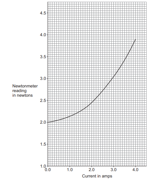
The student recorded the readings on the newtonmeter as the current increased.

Figure 4

Newtonmeter reading (N) on the y-axis (1.0 to 4.5) against Current (A) on the x-axis (0.0 to 4.0). The original line starts at 2.0 N when current = 0 and curves upwards as current increases.

The student wrapped twice as many turns of wire around the iron bar and repeated the investigation.

Draw a line on Figure 4 to show the expected results.

5a
2 marks

This question is about magnetism.

Which two materials are magnetic?

Tick (✓) two boxes.

  • Carbon

  • Cobalt

  • Copper

  • Nickel

  • Sodium

5b
3 marks

Describe how you could find the magnetic field pattern of a permanent bar magnet.

5c
3 marks

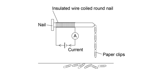
A student investigates how the number of turns of wire on a solenoid affects the strength of the solenoid.

To test the strength of the solenoid she looks at how many paper clips the solenoid could lift.

Figure 3 shows the setup equipment.

She keeps the current through the coil constant throughout the experiment.

Figure 3

(a solenoid coil connected to a power supply, with paper clips hanging from one end)

Table 3 shows the student's results.

Table 3

Number of turns of wire on solenoid

Number of paper clips picked up by solenoid

Test 1

Test 2

Test 3

Mean number of paper clips picked up

0

0

0

0

0

10

4

3

4

4

20

8

8

9

8

30

11

11

13

12

40

15

13

16

15

50

21

24

19

21

60

25

24

26

25

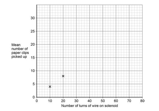
Use the data from Table 3 to complete the graph in Figure 4.

  • The first two points have been plotted for you.

  • Draw a line of best fit.

Figure 4

Scatter graph of mean paper clips picked up versus solenoid turns, showing points at about 10 turns with 4 clips and 20 turns with 8 clips.
5d
2 marks

Describe the pattern shown in the graph.

5e
Sme Calculator
1 mark

Use your graph to predict how many paper clips the solenoid will pick up when 80 turns of wire are used.

Number of paper clips picked up = _________________

6a
2 marks

Explain why this reaction is a redox reaction.

6b
2 marks

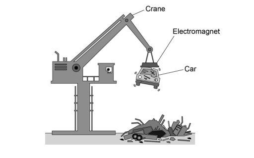
Figure 5 shows an electromagnet being used to lift a car in a scrapyard.

Figure 5

Diagram of a crane using a labelled electromagnet to lift a crushed car above a scrap heap of metal parts

An electromagnet is made up of a solenoid.

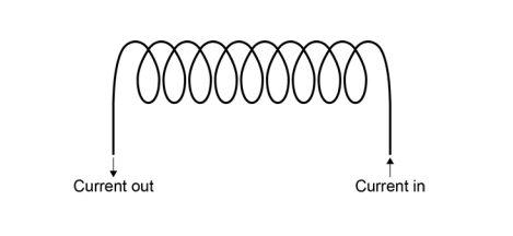
Figure 6 shows a solenoid.

Figure 6

(a coil of wire shown in cross-section with the loops visible).

Draw the magnetic field of the solenoid on Figure 6.

6c
4 marks

In a scrapyard, an electromagnet is used to lift and release cars so they can be moved around.

Suggest two ways a solenoid could be made to lift and release cars in a scrapyard.

Explain why each suggestion would be useful in the scrapyard.

7a
1 mark

The area around a magnet is called the magnetic field.

The Earth has a magnetic field.

What causes the Earth's magnetic field?

Tick (✓) one box.

  • The movement of liquid iron in the Earth's outer core

  • The gravitational field of the Earth

  • The permanent magnet in the Earth's core

7b
2 marks

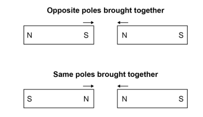
Figure 4

Diagram of two bar magnets showing attraction when opposite poles meet and repulsion when same poles meet, with arrows indicating direction of movement

What will happen in each case when the poles of two magnets are brought close together?

Opposite poles brought together: __________________________

Same poles brought together: ______________________________

7c
4 marks

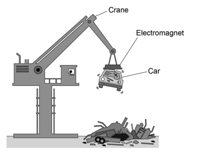
Figure 5 shows an electromagnet being used to lift a car in a scrapyard.

Figure 5

(a large electromagnet suspended from a crane lifting a metal car body).

An electromagnet is a solenoid.

Explain why it is better to use an electromagnet rather than a permanent magnet in a scrapyard.

You should include a comparison of the properties of electromagnets and permanent magnets in your answer.