Electric Circuits (WJEC GCSE Science (Double Award): Physics): Exam Questions

Exam code: 3430

2 hours16 questions
1a
Sme Calculator
6 marks

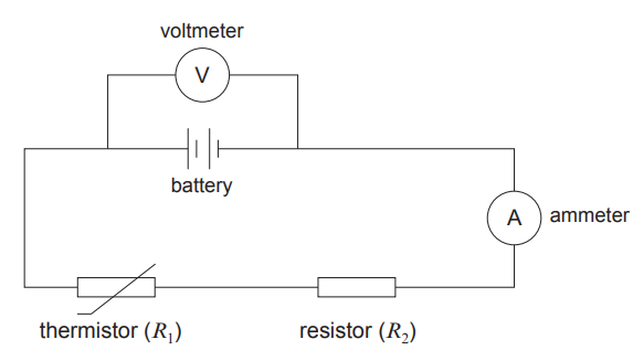
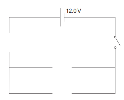
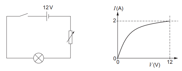
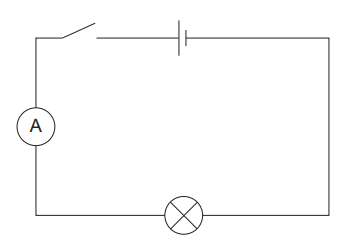
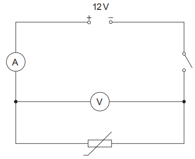
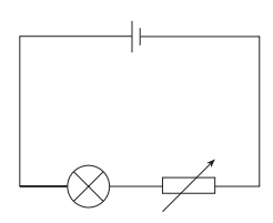
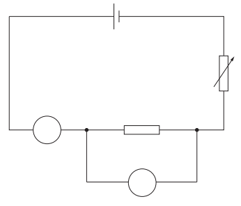
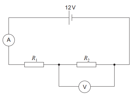
Students set up the following circuit to investigate how the current through a 12 V filament lamp varies with voltage.

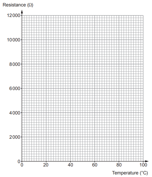
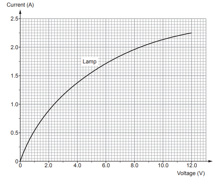
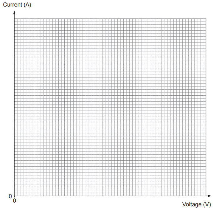
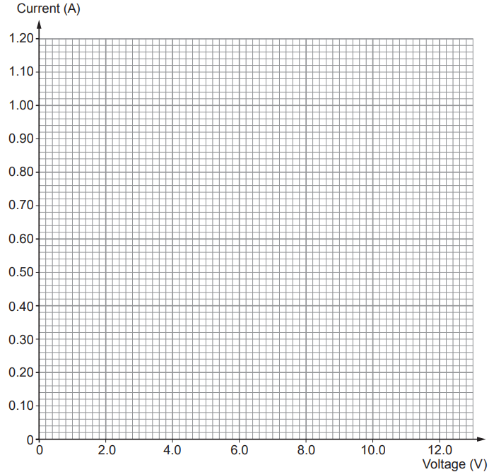
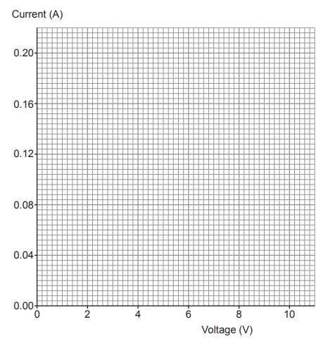
Their results are shown on the graph.

Diagram of a 12 V lamp circuit with switch and variable resistor, alongside a graph of current versus voltage rising to about 2 A at 12 V.

Explain how they use the circuit to produce the results shown.

Include in your answer:

  • what additional components they need to add to the circuit

  • how these components should be connected and what they are used for

  • a method they can use to obtain several pairs of readings.

1b
Sme Calculator
2 marks

George states that the resistance of the lamp decreases as the voltage increases.

Use the graph to explain whether you agree.

2
Sme Calculator
4 marks

The information plate from a hairdryer is shown below.

230 V

50 Hz ac

2300 W

(i) Use the information in the box to complete the sentences below.

I. Mains electricity has a voltage of ..........

[1]

II. The power of the hairdryer is ..........

[1]

(ii) Use your answers to (i) and the equation:

\text{current} = \frac{\text{power}}{\text{voltage}}

to calculate the current in the hairdryer.

[2]

current = .......... A

3a
Sme Calculator
2 marks

A group of pupils investigate the current-voltage (I minus V) characteristics of different components.

The first component they investigate is a lamp.

Part of the circuit used is shown below.

Add a variable resistor and voltmeter to the circuit diagram.

Simple series circuit diagram showing a switch, a cell, an ammeter and a lamp connected in a single loop with standard electrical symbols
3b
Sme Calculator
6 marks

They draw a graph from their results for the lamp. It is shown below.

Graph of a lamp’s current–voltage relationship, showing a curved line from (0,0) to about (12 V, 2.4 A), with current increasing but gradient decreasing

(i) One student suggests that as the current through the lamp doubles the voltage triples.

Use pairs of data within the range 0.5 A to 2.0 A from the graph to explain whether you agree with the student.

[3]

(ii) Use the equation:

power = voltage × current

and information from the graph to calculate the maximum power produced by the lamp.

[3]

Power = .......... W

3c
Sme Calculator
3 marks

The experiment is repeated with a 6 Ω resistor but the results are lost.

(i) Use the equation:

current = \frac{\text{voltage}}{\text{resistance}}

to calculate the current through the 6 Ω resistor at 12 V.

[2]

Current = .......... A

(ii) Draw the line for this resistor on the grid shown in part (b).

[1]

3d
Sme Calculator
4 marks

The students are given a sealed box containing another component.

Diagram of a sealed rectangular box with a single horizontal connecting wire passing straight through from left to right, labelled sealed box and connecting wire

They are asked to confirm whether the hidden component is a diode.

(i) Describe how they would use the circuit shown in part (a) to confirm whether or not it is a diode.

[3]

(ii) Sketch the I minus V graph that you would expect to obtain for a diode on the grid below.

[1]

Simple graph with horizontal axis labelled Voltage and vertical axis labelled Current, crossing at zero in the centre, with arrows indicating positive directions
4
Sme Calculator
6 marks

A group of students set up the following circuit. Their aim is to measure the current through the ammeter and to use it to calculate the currents and voltages in the various parts of the circuit.

Circuit diagram showing a 12 V supply, an ammeter reading 2 A, resistor R1 = 2 Ω in series with a parallel network of R2 = 12 Ω and R3 = 6 Ω

Use an equation(s) from page 2 to answer the following questions.

(i) Calculate the voltage across R1.

[2]

Voltage = .......... V

(ii) Use your answer to part (i) to calculate the current through each of the parallel resistors.

[4]

Current through R2 = .......... A

Current through R3 = .......... A

5a
3 marks

A student is investigating the current-voltage characteristic of a filament lamp. In the space below, draw a circuit diagram of the circuit she would use.

5b
Sme Calculator
6 marks

The student collects the following results.

Voltage (V)

Current (A)

0.0

0.00

2.0

0.40

4.0

0.76

6.0

0.94

10.0

1.08

12.0

1.10

(i) Plot the data on the grid below and draw a suitable line. [3]

Blank grid graph with labelled axes: horizontal axis shows voltage in volts, vertical axis shows current in amperes, origin marked at bottom left.

(ii) She concludes that the resistance of the lamp decreases as voltage increases. Explain using calculations, whether you agree or disagree with this conclusion.

[3]

6a
Sme Calculator
6 marks

A thermistor is a type of resistor whose resistance depends on temperature. Thermistors are often used as temperature sensors. A group of students immerse a thermistor and a thermometer in water in order to determine the resistance at different temperatures. The circuit they use is shown below.

Circuit diagram with 12 V supply, ammeter in series, voltmeter across a variable resistor, and a switch controlling the single-loop circuit

Their results are given below.

Temperature (°C)

Current (mA)

Voltage (V)

Resistance (kΩ)

20

0.97

12.0

12.4

40

2.22

12.0

5.41

60

4.80

12.0

2.50

80

9.23

12.0

1.30

100

17.14

12.0

0.70

(i) Plot the data on the grid below and draw a suitable line.

[4]

Blank Cartesian graph grid with horizontal axis labelled Temperature (°C) and vertical axis labelled Resistance (kΩ), ready for plotting data.

(ii) Describe the relationship between temperature and resistance.

[2]

6b
Sme Calculator
8 marks

(i) A resistor of resistance 5 kΩ is now added to the original circuit, in parallel with the thermistor which is at a temperature of 30 °C. The same 12 V power supply is used. Use your graph and equations to calculate the total current in the circuit.

[5]

Current = .......... A

(ii) Kim suggests that the current through both the resistor and the thermistor will decrease as the thermistor cools down. Explain whether or not she is correct.

[3]

7a
Sme Calculator
4 marks

In class, a group of students set up a simple series circuit as shown in the diagram below.

Simple series circuit with 12 V battery, two ammeters A1 and A2, and two resistors of 2 ohms and 6 ohms connected in line

(i) Use the equation:

R = R_1 + R_2

to calculate the total resistance in the circuit.

[1]

Total resistance = .......... Ω

(ii) Use an equation I = \frac{V}{R} to calculate the current reading on ammeter A1.

[2]

Ammeter A1 reading = .......... A

(iii) State the current reading on ammeter A2.

[1]

Ammeter A2 reading = .......... A

7b
2 marks

The 6 Ω resistor is now removed from the circuit. It is added in parallel with the 2 Ω resistor. The circuit is complete.

Complete the following sentences by underlining the correct phrase or word.

(i) The total resistance of the circuit (increases / stays the same / decreases).

[1]

(ii) The current reading on the ammeter A1 (increases / stays the same / decreases).

[1]

8a
5 marks

Students are investigating the current-voltage characteristic of a filament lamp. An incomplete diagram of their circuit is shown below.

Simple circuit diagram showing a cell powering a lamp and a variable resistor connected in series with connecting wires forming a complete loop

(i) Add to the diagram a correctly connected ammeter and voltmeter.

[2]

(ii) Describe how the circuit is used to obtain a series of measurements of current and voltage.

[3]

8b
3 marks

The following data were collected using the circuit.

Voltage (V)

Current (A)

0.0

0.00

2.0

0.46

4.0

0.76

6.0

0.94

8.0

1.02

10.0

1.06

12.0

1.08

Plot the data on the grid below and draw a suitable line.

Blank Cartesian graph with fine grid; x-axis labelled Voltage (V) from 0 to 12, y-axis labelled Current (A) from 0 to 1.20, no data plotted
8c
Sme Calculator
4 marks

(i) Use the graph and the equation:

resistance = \frac{\text{voltage}}{\text{current}}

to calculate the resistance of the lamp when the voltage across it is 3 V.

[2]

Resistance = .......... Ω

(ii) The students conclude that the resistance of the lamp increases as voltage increases. Explain how the data support this conclusion.

[2]

9a
Sme Calculator
1 mark

Students investigate the I minus V characteristic of a resistor.

They set up the following circuit.

Simple series–parallel circuit with a cell, variable resistor, fixed resistor and two lamps, one lamp in series and the other in a parallel branch.

Complete the circuit by labelling the ammeter and voltmeter with their correct symbols.

9b
Sme Calculator
9 marks

The students' results are given in the table below.

Voltage (V)

Current (A)

0

0.00

2

0.04

3

0.06

5

0.10

8

0.16

10

0.20

(i) Plot the data on the grid below and draw a suitable line.

[3]

Blank Cartesian graph with Voltage (V) on the x-axis from 0 to 10 and Current (A) on the y-axis from 0.00 to 0.20, showing no plotted data points

(ii) Use the graph to determine the current at 4 V.

[1]

current = .......... A

(iii) Use the equation:

\text{resistance} = \frac{\text{voltage}}{\text{current}}

to determine the resistance of the resistor at 4 V.

[2]

resistance = .......... Ω

(iv) Sally suggests that the resistance of the resistor is constant.

Use the graph to explain whether you agree.

[1]

(v) In the circuit, the resistance of the variable resistor is set at 25 Ω.

Use your answer to part (b)(iii) and an equation to calculate the total resistance of the circuit.

[2]

total resistance = .......... Ω

10
Sme Calculator
2 marks

The circuit diagram below shows a design for a hairdryer that can blow either cold air or hot air.

The switches in the diagram are in the open position.

Diagram of an a.c. mains circuit with fuse, switch 1 controlling a fan motor, and switch 2 controlling a heater connected in parallel.

Complete the following sentences by underlining the correct phrase in the brackets.

When switch 1 is closed and switch 2 is open the hairdryer blows cold air because (only the fan is on / only the heater is on / the heater and fan are both on).

The hairdryer blows hot air when the heater and fan are both on. This happens when (both switches are open / only switch 2 is closed / both switches are closed).

11a
Sme Calculator
7 marks

The circuit shown below contains two identical resistors connected in parallel.

Each resistor has a resistance of 10 Ω.

Circuit diagram with 12 V supply, ammeter in series, resistor R1 in upper branch, resistor R2 in lower branch, and voltmeter across R2.

(i) Use the equation:

\frac{1}{R_{\text{total}}} = \frac{1}{R_1} + \frac{1}{R_2}

to calculate the total resistance of the circuit.

[2]

total resistance =..................Ω

(ii) Use an equation from the equations sheet to calculate the current reading on the ammeter.

[2]

current =.........................A

(iii) State the voltage across R subscript 2.

[1]

voltage =......................... V

(iv) Calculate the current through R subscript 2.

[2]

current =...........................A

11b
Sme Calculator
4 marks

The same resistors are now connected in series.

Circuit diagram with 12 V battery, ammeter in series, two series resistors R1 and R2, and a voltmeter connected in parallel across resistor R2

State how the following values compare with the parallel circuit in part (a).

(i) The total resistance of the circuit.

[1]

(ii) The current reading on the ammeter.

[1]

(iii) I. The voltage across R2.

[1]

II. Give a reason for your answer.

[1]

12a
Sme Calculator
9 marks

A group of students set up the following circuit.

Circuit diagram with 9 V battery, ammeter, resistor R3 and parallel resistors R1 = 12 Ω and R2 = 6 Ω in a single loop.

(i) Use the equation:

\frac{1}{R} = \frac{1}{R_{1}} + \frac{1}{R_{2}}

to calculate the total resistance of resistors R subscript 1 and R subscript 2 in parallel.

[3]

total resistance of R subscript 1 and R subscript 2 = .......... Ω

(ii) The total resistance of the circuit is 6 Ω.

Use an equation to calculate the resistance of resistor R subscript 3.

[1]

resistance of R subscript 3 = .......... Ω

(iii) Use an equation to calculate the current through the ammeter.

[2]

current = .......... A

(iv) Calculate the voltage across the resistor R subscript 3.

[3]

voltage across R subscript 3 = .......... V

12b
Sme Calculator
3 marks

One of the students, Katrina, connects a different circuit, without R1 and R2.

The circuit only contains R3 in series with the battery.

She correctly calculates that the current from the battery would be 4.5 A.

She claims that the new circuit would transfer 45 J of energy in 10 s.

By using equations , explain whether her claim is correct.

13a
Sme Calculator
5 marks

Students set up the temperature sensing circuit shown below.

Circuit diagram showing a battery, thermistor R1 and resistor R2 in series with an ammeter, and a voltmeter connected in parallel across the battery

At a temperature of 20 °C the resistance of the thermistor (R₁) is 300 Ω.

The resistor (R₂) has a fixed resistance of 50 Ω.

(i) Use the equation:

R = R_1 + R_2

to calculate the total resistance (R) of the circuit at 20 °C.

[1]

total resistance = .......... Ω

(ii) A photograph of the voltmeter used in the circuit is shown below.

Analogue voltmeter with a black case, showing a scale from 0 to 10 volts and a needle pointing to about 6 volts

State the voltage shown on the voltmeter.

[1]

voltage = .......... V

(iii) Use your answers from parts (i) and (ii) to calculate the current in the circuit.

[2]

current = .......... A

(iv) State the ammeter reading.

[1]

ammeter reading = .......... A

13b
Sme Calculator
3 marks

Complete the following sentences by underlining the correct phrase or word.

As the (temperature / power / voltage) of the thermistor is increased to 50 °C its resistance decreases. The total resistance in the circuit (increases / stays the same / decreases) and the circuit current (increases / stays the same / decreases).

13c
Sme Calculator
2 marks

(i) State how the original circuit could be changed to become a light sensing circuit.

[1]

(ii) Give a reason for your answer.

[1]

14a
Sme Calculator
3 marks

A thermistor is a type of resistor whose resistance changes with temperature. Thermistors are used as temperature sensors.

To investigate a thermistor, students set up the following circuit to take measurements of current through the thermistor and the voltage across it.

Simple circuit diagram showing a 12.0 V battery connected in series with an open switch and empty parallel branches awaiting components

Complete the circuit diagram using the correct circuit symbols.

14b
Sme Calculator
5 marks

The students place the thermistor in water. They take current and voltage readings at different temperatures. These are used to calculate the resistance of the thermistor at each temperature. The results are shown in the table below.

Temperature (°C)

Current (mA)

Voltage (V)

Resistance (Ω)

20

1.0

12.0

12 000

40

2.2

12.0

5 400

60

4.8

12.0

2 500

80

8.6

12.0

1 400

100

20.0

12.0

600

(i) Plot the data on the grid below and draw a suitable line.

[3]

Blank Cartesian graph with gridlines, x-axis labelled Temperature (°C) from 0–100 and y-axis labelled Resistance (Ω) from 0–12000, no data plotted

(ii) Describe what happens to the resistance of the thermistor as the temperature increases.

[2]

14c
Sme Calculator
4 marks

(i) Use your graph to find the resistance of the thermistor at 50 °C.

[1]

Resistance at 50 °C = .......... Ω

(ii) Use an equation I = V/R to calculate the current through the thermistor at 50 °C.

[3]

Current = .......... A

14d
Sme Calculator
2 marks

A temperature sensor needs to vary in resistance by at least 3 600 Ω as the temperature changes from 40 °C to 80 °C. Use the results from the experiment to explain whether the thermistor used by the students would be suitable.

15
Sme Calculator
7 marks

(i) The input power to the biomass power station is 20.0 MW.

Use an equation E space equals space P cross times t to calculate how much energy is transferred by burning wood in the power station every 60 minutes.

Give your answer in MJ.

[3]

energy transferred every 60 minutes = .......... MJ

(ii) Burning 1 tonne of the wood used in the biomass power station produces 2880 MJ of energy.

Calculate how many tonnes of wood the biomass power station burns every 60 minutes.

[1]

mass of wood burned every 60 minutes = .......... tonnes

(iii) The wood used in the biomass power station has a density of 500 kg/m³.

Use the equation:

\text{volume} = \frac{\text{mass}}{\text{density}}

to determine the volume of wood burned every 60 minutes.

1 tonne = 1000 kg.

[2]

volume of wood burned every 60 minutes = .......... m³

(iv) An average tree produces 5 m³ of wood.

Calculate how many trees are burned every 60 minutes.

[1]

number of trees burned every 60 minutes = ..........

16
Sme Calculator
2 marks

The wind turbines have a maximum power output of 13.6 MW.

They provide energy to the water when slowly pumping it to a higher level.

When needed, the hydroelectric pumped storage system can quickly generate electricity.

Scientists state it is possible to get a greater power from the hydroelectric pumped storage system (16 MW) than the power supplied to it by the wind turbines.

By considering the equation:

\text{power} = \frac{\text{energy transferred}}{\text{time}}

explain why the claim is true.