Current, Potential Difference & Resistance (Edexcel IGCSE Science (Double Award) (Modular): Physics Unit 1): Exam Questions

Exam code: 4XSD1

2 hours15 questions
1a
1 mark

The diagram shows some electrical circuit symbols.

Four electrical circuit symbols labelled A to D. A is an open switch: a horizontal wire with a small circle on each side of a gap, and a straight arm pivoted on the left circle and lifted away from the right circle. B is a diode: a horizontal wire with a solid triangle pointing to the right, its tip touching a short vertical bar. C is a filament lamp: a horizontal wire passing through a circle that contains a cross. D is a variable resistor: a horizontal wire passing through a rectangle, with a long arrow drawn diagonally across the rectangle pointing up to the right.

Which symbol represents a switch?

  • A

  • B

  • C

  • D

1b
1 mark

Which of the symbols in (a) represents a component that only allows current to flow in one direction?

  • A

  • B

  • C

  • D

1c
1 mark

Which of the symbols in (a) represents a component that can have its resistance varied by varying the length of wire?

  • A

  • B

  • C

  • D

2a
3 marks

This question is about electrical components.

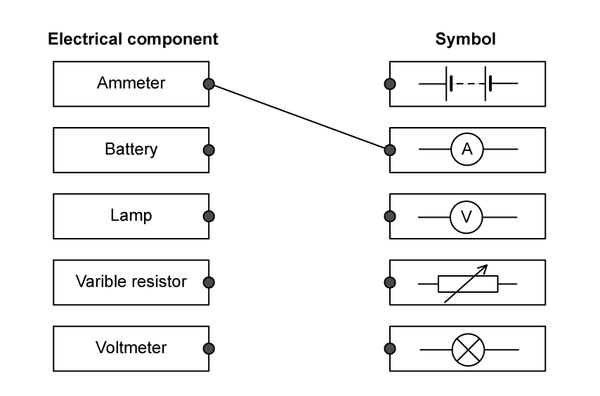
Draw a straight line from each electrical component to its correct symbol.

One has been done for you.

Matching exercise in two columns. The left column, headed electrical component, has five boxes reading ammeter, battery, lamp, variable resistor and voltmeter, each with a dot on its right-hand edge. The right column, headed symbol, has five boxes each with a dot on its left-hand edge, containing in order: two cells side by side, a circle containing the letter A, a circle containing the letter V, a rectangle crossed by a diagonal arrow, and a circle containing a cross. One line is already drawn, joining ammeter to the circle containing the letter A.
2b
2 marks

(i) Name an electrical component whose resistance decreases when it is moved into brighter light.

[1]

(ii) Name an electrical component whose resistance decreases as its temperature increases.

[1]

2c
1 mark

Which of the following is the correct symbol for a thermistor?

Table of four circuit symbols labelled A to D, each drawn on a horizontal wire. A is a rectangle with a horizontal line running through it. B is a plain rectangle. C is a rectangle crossed by a long diagonal arrow pointing down to the left. D is a rectangle crossed by a diagonal line that turns horizontal at its lower end.
  • A

  • B

  • C

  • D

3a
3 marks

A washing machine has an electric motor and an electric heater.

A woman loading clothes into a top-loading washing machine in a kitchen, with a young child sitting on the open lid of the machine beside her

The resistance of the heater is 22 Ω.

The mains voltage is 230 V.

(i) State the equation linking voltage, current and resistance.

[1]

(ii) Show that the current in the heater is about 10 A when it is working.

[2]

3b
4 marks

The washing machine is fitted with a fuse rated at 13 A.

(i) Explain why the washing machine is fitted with a fuse.

[2]

(ii) When the motor is working, the current in it is 1.74 A.

Explain why it would not be sensible to replace the 13 A fuse with a 2 A fuse.

[2]

4a
1 mark

Which quantity is defined as the rate of flow of charge? 

  • voltage

  • current

  • power

  • resistance

4b
1 mark

Which quantity is defined as the energy transferred per unit charge passed?

  • voltage

  • current

  • power

  • resistance

5a
1 mark

The current in the wires of a circuit is a flow of particles.

What is the name of these particles?

  • electrons

  • positrons

  • protons

  • atoms

5b
4 marks

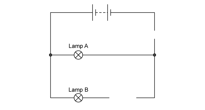
A student sets up an electrical circuit. The diagram shows part of this circuit.

Incomplete circuit diagram. A battery of two cells sits across the top. Lamp A is on a horizontal branch in the middle and lamp B is on a lower horizontal branch, so the two lamps are in parallel with each other. There is a gap in the right-hand wire between the battery and the lamp A branch, and a second gap in the lamp B branch to the right of lamp B.

Complete the circuit diagram by drawing circuit symbols for three devices so that the student can

(i) Measure the total current in the circuit

[1]

(ii) Vary the current in the lamp B only

[1]

(iii) Measure the voltage across lamp B.

[2]

5c
3 marks

The current in lamp A is 0.20 A. The voltage across lamp A is 6.0 V.

(i) State the equation linking voltage, current and resistance.

[1]

(ii) Calculate the resistance of lamp A.

[2]

resistance = ......................................................Ω

1
1 mark

The current in a metalic conductor is a flow of

  • negatively charged electrons

  • negatively charged protons

  • positively charged electrons

  • positively charged protons

2a
4 marks

The photograph shows a solar-powered battery charger connected to a mobile phone.

Greyscale photograph of a flat rectangular solar battery charger, labelled battery charger, with a grid of photovoltaic strips covering its upper face. A short USB cable, labelled cable, runs from a socket on the charger to the base of a smartphone, labelled mobile phone, whose screen shows a battery charging icon.

When the battery charger is used, it transfers light energy from the Sun to the battery of the mobile phone.

It takes 3.5 hours to recharge the battery fully. The average current supplied by the charger is 400 mA.

(i) State the equation linking charge, current and time.

[1]

(ii) Calculate the amount of charge needed to recharge the battery fully, and give the unit.

[3]

2b
2 marks

If the charger is moved into the shade, the output power decreases. The voltage across the charger stays the same.

Explain how moving the charger into the shade affects the time needed to recharge the battery fully.  

3a
5 marks

An electric vehicle has a rechargeable battery.

The battery is recharged by connecting it to a charging station.

Black and white photograph of a white electric sports car parked in a charging bay. A cable runs from a charging station on the left to a charging port near the rear of the car. A partly obscured word POINT is painted on the ground of the bay.

©Epattlomer

The battery voltage is 385 V.

(i) State the amount of energy transferred when one coulomb of charge passes through a potential difference of 385 V.

[1]

energy transferred = ............................. J

(ii) Show that, when a charge of 180 000 C passes through the battery, the total amount of energy transferred to the battery is about 70 MJ.

[2]

(iii) During the charging process, energy is also transferred to the charging station from the mains supply.

Explain why the amount of energy transferred from the mains supply is more than 70 MJ.

[2]

3b
4 marks

Charging takes 110 minutes and causes a total charge of 180 000 C to pass through the battery.

(i) State the equation linking charge, current and time.

[1]

(ii) Calculate the average charging current in the battery.

[3]

current = ........................ A

4a
3 marks

A student investigates the resistance of a lamp.

The student uses a circuit that contains an ammeter, a battery, a lamp and a voltmeter to determine the resistance of the lamp.

Draw a circuit diagram to show how he should connect the apparatus.

4b
1 mark

State the relationship between voltage, current and resistance.

4c
3 marks

The student obtains this graph for a filament lamp.

Graph of current in A against voltage in V for a filament lamp. The curve starts at the origin and rises in a straight line to about 1.0 A at 4 V, then curves gradually, passing through 1.5 A at 6 V and reaching 2.0 A at 12 V. The vertical axis runs from 0 to 2.0 A in steps of 0.5 A and the horizontal axis from 0 to 12 V in steps of 2 V

Calculate the resistance of the lamp when the voltage is 6.0 V.

Give the unit.

resistance = .................... unit = ..............

4d
2 marks

The student reverses the battery connections and then repeats his measurements.

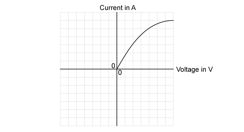
On the axes below, sketch the graph that he would obtain.

Part of the graph has been done for you.

Grid of 14 by 14 squares with a vertical axis labelled current in A and a horizontal axis labelled voltage in V crossing at the centre of the grid, with zero marked at the origin on both axes. A curve is already drawn in the upper right quadrant, rising steeply and in a straight line from the origin, then curving gently to level off near the top right corner of the grid
5a
3 marks

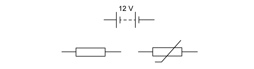
A student is investigating the variation of resistance and temperature in a thermistor. The diagram shows part of the circuit the student intends to use.

Three separate circuit symbols that are not joined by any wires: at the top a battery of two cells labelled 12 V, at the lower left a fixed resistor drawn as a plain rectangle, and at the lower right a thermistor drawn as a rectangle crossed by a long diagonal line. Each component has a short lead on either side but no wires connect them to one another.

Complete the circuit diagram to show how the student should connect the apparatus, including a voltmeter and an ammeter.

5b
3 marks

The student chooses a fixed resistor with a resistance of 5 kΩ. The reading on the ammeter is 0.8 mA.

(i) State the equation linking voltage, current and resistance.

[1]

(ii) Calculate the voltage across the 5 kΩ resistor.

[2]

Voltage = ............................... V

5c
3 marks

The manufacturer's guide states that the thermistor has a resistance of 12 kΩ at room temperature.

The student wants to confirm the accuracy of this value before starting the investigation.

At room temperature, the voltmeter shows a reading of 8 V. 

Determine if this reading is consistent with the manufacturer's value of resistance. 

1a
1 mark

The diagram shows an electric circuit containing a fixed resistor and an LDR.

A series circuit drawn as a single loop. A battery labelled 12 V sits in the top wire. On the left-hand wire an arrow pointing downwards is labelled 45 mA. Along the bottom wire, two components are connected in series with the battery: on the left a light-dependent resistor, drawn as a rectangle inside a circle with two arrows pointing towards it and labelled 150 Ω, and on the right a fixed resistor, drawn as a plain rectangle with no value marked.

A student plans to use a voltmeter and an ammeter in his circuit.

How should the student connect the voltmeter and the ammeter within the circuit?

    • Voltmeter in parallel across the power supply

    • Ammeter in parallel across the LDR

    • Voltmeter in parallel across the LDR

    • Ammeter in series with the LDR

    • Voltmeter in series with the power supply

    • Ammeter in series with the LDR

    • Voltmeter in series with the LDR

    • Ammeter in parallel across the LDR

1b
5 marks

When the LDR is illuminated, its resistance is 150 Ω.

Show that the resistance of the fixed resistor is about 120 Ω.

2a
10 marks

The diagram shows a heater coil and a resistor connected to a 12 V battery and an ammeter.

Circuit diagram of a single series loop containing a 12 V battery drawn as a battery of cells, an ammeter labelled A reading 1.2 A, a 4.0 Ω resistor drawn as a rectangle, and a heater coil drawn as a helical coil. The heater coil is immersed in water in an open container, with labels pointing to the heater coil and to the water. All components are in series, so the ammeter reads the same current through the resistor and the heater coil.

The ammeter reading is 1.2 A.

(i) State the equation linking voltage, current and resistance.

[1]

(ii) Calculate the voltage across the 4.0 Ω resistor.

[2]

voltage = ................... V

(iii) Show that the voltage across the heater coil is about 7 V.

[2]

(iv) Calculate the energy transferred to the heater coil in 5.0 minutes.

[3]

energy transferred = ................... J

(v) At first, the temperature of the water increases. After a while, the temperature reaches a steady value below the boiling point of water.

Explain why the temperature reaches a steady value.

[2]

2b
4 marks

Resistors can be used as heating elements in the rear windows of cars. The diagram shows two possible designs.

Two circuit designs labelled X and Y, each drawn with four identical resistors shown as rectangles. In design X the four resistors are joined end to end in one continuous series chain that snakes back and forth. In design Y the four resistors are connected side by side in parallel between two vertical connecting rails.

(i) Complete the table by placing a tick (✓) in the correct boxes.

Design

Series

Parallel

X

Y

[1]

(ii) Describe the advantages and disadvantages of design X when used as a heater in a car window.

[3]

3a
3 marks

The diagram shows a van der Graaff generator, a device that can reach extremely high voltages.

Line diagram of a Van de Graaff generator. A large hollow metal dome sits on top of a vertical column and is covered in plus signs showing positive charge. Inside the column a belt passes over a black roller in the base unit and up over a small pulley inside the dome, carrying plus signs upwards; arrows show the belt moving up on the left side and down on the right. A jagged spark jumps from the right-hand side of the dome to a smaller grey sphere mounted on an inclined rod. The grey sphere, and the curved earthing wire running from it back to the base unit, are marked with minus signs showing negative charge.

Calculate the energy transferred to an electron when it passes through a voltage of 180 kV.

Charge of an electron = 1.6 × 10⁻¹⁹ C

energy transferred = ........................................ J

3b
6 marks

When the van der Graaff generator is fully charged, it stores 3.5 × 10⁻⁸ C of charge.

(i) Calculate the number of electrons stored on a fully charged van der Graaff generator.

[2]

number of electrons = ..............................................................

(ii) The charge on the generator discharges through the air as a spark.

The charge takes a time of 0.56 ms to leave the generator.

Calculate the mean (average) current in the air. Give the unit.

[4]

mean current = ......................... unit .................

4a
1 mark

The diagram shows a current-voltage graph for a resistor and for a lamp.

Current-voltage graph with current in amps from 0 to 6.0 on the vertical axis and voltage in volts from 0 to 8.4 on the horizontal axis. Two lines both start at the origin. The line labelled Lamp curves upwards steeply at first and then flattens, passing through about 3.0 A at 3.0 V and about 4.4 A at 6.0 V, and reaching about 4.8 A at 8.4 V. The line labelled Resistor is straight, passing through 2.0 A at 3.0 V and 4.0 A at 6.0 V, and reaching about 5.6 A at 8.4 V. The two lines cross at about 6.9 V

The voltage applied to the resistor is increased.

What is the effect on the resistance of the resistor?

  • resistance increases

  • resistance decreases

  • resistance increases and decreases

  • resistance stays the same

4b
1 mark

The voltage applied to the lamp is increased. 

What is the effect on the resistance of the lamp?

  • resistance increases

  • resistance decreases

  • resistance increases and decreases

  • resistance stays the same

4c
5 marks

The p.d. across the lamp is 6.0 V.

(i) Calculate the resistance of the lamp.

[3]

resistance = ......................................................... Ω

(ii) The lamp and the resistor are connected in parallel to a 6.0 V supply.

Calculate the current from the supply.

[2]

current = ......................................................... A

4d
2 marks

The lamp and the resistor are connected in series to another power supply. The current in the circuit is 4.0 A.

Calculate the total voltage across the lamp and the resistor.

  voltage = ......................................................... V

5a
4 marks

A light-emitting diode (LED) is a diode that emits light when there is a current in it. 

Draw a circuit diagram showing an LED, connected so that it is lit, in series with a battery and a fixed resistor.

5b
6 marks

The voltage across the LED when lit is 3.1 V and the current in the LED is 0.030 A.

(i) Add to the diagram in (a) to show how these readings were obtained.

[2]

(ii) Calculate the value of the resistance of the LED when lit.

[2]

resistance = ......................................................... Ω

(iii) An identical LED is connected in series with the first LED.

State and explain the effect on the readings of voltage and current.

[2]

5c
5 marks

The diagram shows a power supply with a voltage of 12 V connected in series with a lamp and a heater.

Circuit diagram of a single series loop. At the top of the loop are the two terminals of the power supply, drawn as two small open circles facing each other across a gap. From the left-hand terminal the wire runs down the left-hand side and along the bottom to a lamp, drawn as a circle with a cross inside it, then continues along the bottom to a heater, drawn as a rectangle divided into four equal sections, then up the right-hand side back to the right-hand terminal. The lamp and the heater are connected in series with each other and with the power supply.

The voltage across the lamp is 3.2 V and the current in the lamp is 1.5 A.

(i) Calculate the resistance of the heater.

[3]

resistance = ......................................................... Ω

(ii) Calculate the power of the heater.

[2]

power = ......................................................... W