Electric Circuits (Cambridge (CIE) O Level Physics): Exam Questions

Exam code: 5054

3 hours40 questions
1
7 marks

A student investigates a wind turbine, which is an electrical generator driven by a propeller blade.

Plan an experiment which will enable him to investigate how the current in a resistor connected across the terminals of the turbine varies with the speed of the air flow through the turbine.

The apparatus available includes:

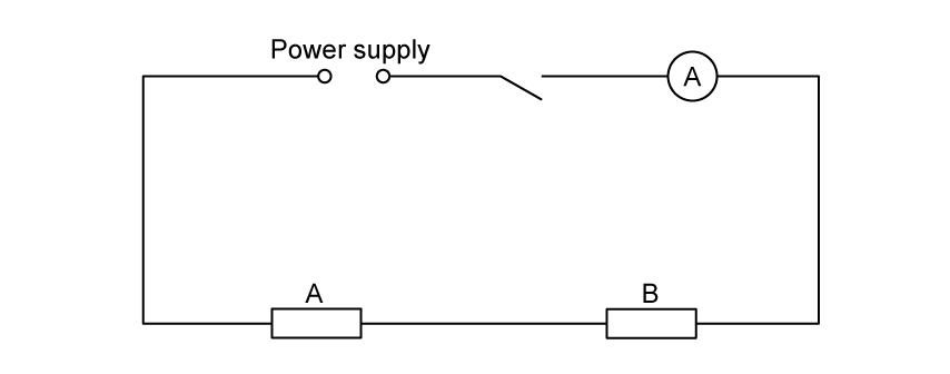
  • a model wind turbine as shown in Fig. 4.1

  • an electric fan to provide the moving air to turn the turbine

  • a device for measuring air speed.

In your plan, you should:

  • list any additional apparatus needed

  • complete the wind turbine circuit diagram on Fig. 4.1

  • state the key variables to be kept constant

  • explain briefly how to carry out the experiment, including how the speed of the air flow is to be changed

  • explain how to use the readings to reach a conclusion.

6sSLF4yz_q4
2a
4 marks

A student determines the resistances of some filament lamps.

Fig. 2.1 shows the first circuit she uses. 

p6-circuit

(i) Record the potential difference V subscript 1 across the lamp L1, as shown on the voltmeter in Fig. 2.2.

p6-meters

V subscript 1 = .................................................. V [1]

(ii) Record the current I subscript 1 in the circuit, as shown in Fig. 2.3.    

I subscript 1 = .................................................. A [1]

(iii) Calculate the resistance R subscript 1 of the filament of lamp L1. Use the equation R subscript 1 equals V subscript 1 over I subscript 1 . Include the unit.

R subscript 1 = ..................................................... [2]

2b
1 mark

The student disconnects the voltmeter. She connects lamp L2 in series with lamp L1. She connects the voltmeter across lamp L2.

She measures the current I subscript 2 in the circuit and the potential difference V subscript 2 across lamp L2.

I subscript 2 = ..... 0.30 A .....

V subscript 2 = ..... 1.7 V .....

Calculate the resistance R2 of the filament of lamp L2. Use the equation R subscript 2 equals V subscript 2 over I subscript 2.

R subscript 2 = .............................................

The student disconnects the voltmeter. She connects lamp L3 in series with lamps L1 and L2. She connects the voltmeter across lamp L3.

She measures the current I subscript 3 in the circuit and the potential difference V subscript 3 across lamp L3.            

I subscript 2 = ..... 0.26 A .....

V subscript 2 = ..... 1.2 V .....

Calculate the resistance R3 of the filament of lamp L3. Use the equation R subscript 3 equals V subscript 3 over I subscript 3.

R subscript 3 = ...................................

2c
1 mark

Calculate R1 + R2 + R3. Give your answer to a suitable number of significant figures for this experiment.

    R1 + R2 + R3 = ..................................................... 

2d
2 marks

Some students make suggestions about the results of the experiment.

Suggestion AR1 + R2 + R3 should be equal to 3 × R1

Suggestion BR1 + R2 + R3 should be less than 3 × R1

Suggestion CR1 + R2 + R3 should be greater than 3 × R1

State which suggestion A, B or C agrees with your results. Justify your answer by reference to your results.

2e
3 marks

Draw a circuit diagram to show the circuit used in part (b) with all three lamps connected in series.

3a
1 mark

A student is investigating a circuit containing different lamps.

She is using the circuit shown in Fig. 3.1.

atp-4

On Fig. 3.1, draw a voltmeter connected so that it measures the potential difference (p.d.) across lamp X.

3b
1 mark

The student uses the ammeter to measure the current in the circuit.

atp-5

Record the current IS in the circuit, as shown in Fig. 3.2.

IS = ............................................................

3c
4 marks

(i) The student uses the voltmeter to measure the p.d. VX across lamp X and then reconnects the voltmeter to measure the p.d. VY across lamp Y.  

atp-6

Record the value of the p.d. VX  across lamp X, shown in Fig. 3.3.

VX  = ...............................................................

Record the value of the p.d. VY across lamp Y, shown in Fig. 3.4.

VY  = ...............................................................

[1]

(ii) She then measures the p.d. VS across both lamps in series.   

atp-7

Record the value of the p.d. VS across both lamps in series, shown in Fig. 3.5.

VS  = ...............................................................[1]

(iii) A student suggests that VS should be equal to (VX + VY).

State whether the readings support this suggestion. Justify your statement with reference to the results.

[2]

3d
1 mark

Calculate the resistance R1 of lamp X. Use the readings from (b) and (c)(i) and the equation

R subscript 1 space equals space V subscript X over I subscript S.  

R1 = ......................................................Ω

3e
4 marks

(i) The circuit components are to be rearranged so that

  • lamps X and Y are connected in parallel

  • the ammeter measures the current in lamp X only

  • the voltmeter measures the p.d. across the lamps.

Draw a circuit diagram of this arrangement.

[2]

(ii) The student sets up the circuit as described in (e)(i).  

She measures and records the current in lamp X and the p.d. across the lamps.  

She then calculates a new resistance R2 for lamp X in this parallel circuit.  

R2 = 8.3 Ω

The student notices that lamp X is very bright in this parallel circuit, but it was dim in the series circuit in (a).

Suggest how temperature affects the resistance of a lamp.

Justify your suggestion by reference to the value of R1 from (d) and the value of R2.

[2]

4a
1 mark

A student investigates the resistance of resistors connected in series.

Fig. 2.1 shows the circuit used.

A circuit diagram showing a power supply, an open switch, an ammeter, and two resistors labelled A and B connected in series.

Fig. 2.1

On Fig. 2.1, draw a voltmeter connected to measure the potential difference across resistor A.

4b
2 marks

The student closes the switch and records the potential difference V subscript straight A across resistor A and current I in the circuit. The meter readings are shown in Fig. 2.2.

Left: An analogue voltmeter showing a 0-10 V scale with 0.2 V divisions and a needle pointing to 2 divisions after 1 V. Right: An analogue ammeter showing a 0-1.0 A scale with 0.02 A divisions and a needle pointing to 3 divisions after 0.2 A.

Fig. 2.2

Record the potential difference V subscript straight A and current I.

4c
Sme Calculator
2 marks

Calculate the resistance R subscript straight A of resistor A using the equation R subscript straight A space equals space V subscript straight A over I.

Give your answer to a suitable number of significant figures for this experiment.

4d
Sme Calculator
1 mark

The student then connects the voltmeter to measure the potential difference across both resistors A and B. The new potential difference reading is V subscript AB space equals space 2.6 text  V end text.

Calculate the combined resistance R subscript AB of the two resistors in series.

4e
2 marks

The resistance of resistor B is known to be R subscript straight B space equals space 4.5 space straight capital omega.

A student suggests that R subscript AB should be equal to R subscript straight A space plus space R subscript straight B.

State whether your results support this suggestion. Justify your answer by reference to your values.

4f
3 marks

(i) The student wants to repeat the experiment with resistor A and resistor B connected in parallel.

Complete the circuit diagram in Fig. 2.3 to show this arrangement.

[1]

An incomplete circuit diagram showing the power supply, switch, and ammeter, with a gap where the parallel resistors should be drawn.

Fig. 2.3

(ii) The student notices that the resistors become warm during the experiment.

State one change they could make to the procedure to reduce this heating effect.

[1]

(iii) State one hazard associated with wires overheating in a circuit.

[1]