E.m.f & Internal Resistance (OCR A Level Physics): Structured Questions

Exam code: H556

32 mins9 questions
1a
8 marks

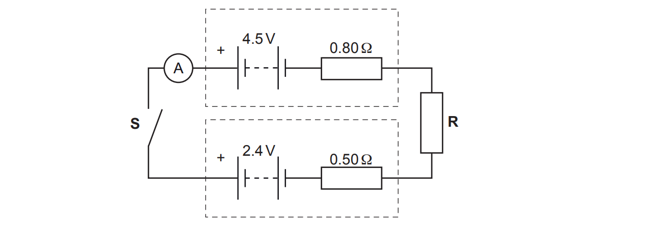
The circuit diagram of an electrical circuit is shown below.
Circuit diagram of a single loop. Along the top: an ammeter A, then a battery labelled 4.5 V with its positive terminal on the left, then a 0.80 Ω resistor; the battery and the 0.80 Ω resistor are enclosed in a dashed box. Along the bottom: a battery labelled 2.4 V with its positive terminal on the left, then a 0.50 Ω resistor, also enclosed in a dashed box. On the right, a resistor labelled R joins the two right-hand ends. On the left, an open switch labelled S joins the ammeter to the bottom wire.

The positive terminals of the batteries are connected together.

One battery has electromotive force (e.m.f.) 4.5 V and internal resistance 0.80 Ω.

The other battery has e.m.f. 2.4 V and internal resistance 0.50 Ω.

R is a coil of insulated wire of resistance 1.2 Ω at room temperature.

The switch S is closed.

(i) On the diagram, draw an arrow to show the direction of the conventional current.

[1]

(ii) Calculate the current I shown by the ammeter.

I = ...................................................... A

[3]

(iii) The insulated wire has diameter 4.6 × 10⁻⁴ m.

The number density of charge carriers in R is 4.2 × 1028 m−3.

Calculate the mean drift velocity v of the charge carriers in R.

v = ...................................................... m s−1

[2]

(iv) The current measured by the ammeter is smaller than that calculated in (ii). This is because the temperature of R increased due to heating by the current.

Without any changes to the circuit itself, state and explain what practically can be done to make the measured current the same as the calculated current.

[2]

1b
6 marks

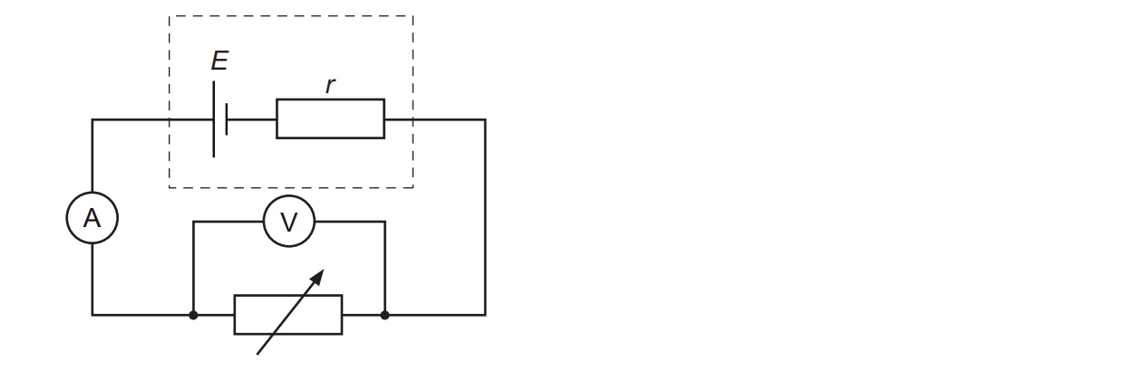
A student is doing an experiment to determine the e.m.f. E of a cell and its internal resistance r.

The circuit diagram of the arrangement is shown below.
Circuit diagram. A cell of e.m.f. E and a resistor labelled r are drawn together inside a dashed box. The cell is connected in series with an ammeter A and a variable resistor. A voltmeter V is connected in parallel across the variable resistor only.

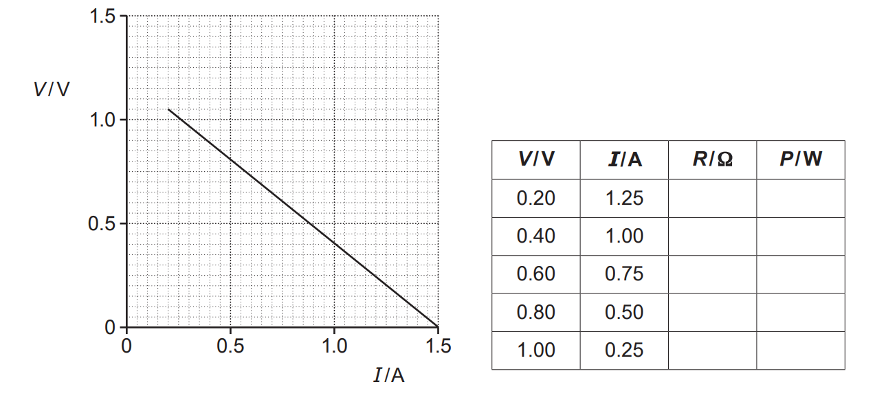
The student changes the resistance of the variable resistor. The potential difference V across the variable resistor and the current I in the circuit are measured.

The V against I graph plotted by the student is shown below.
Left: a graph of V / V, from 0 to 1.5, against I / A, from 0 to 1.5, on a fine grid. A straight line falls from about I = 0.2 A, V = 1.05 V to I = 1.5 A, V = 0, passing through I = 0.5 A, V = 0.80 V and I = 1.0 A, V = 0.40 V. The line is not drawn as far as the V axis. Right: a table with four columns headed V / V, I / A, R / Ω and P / W. The V and I columns hold five pairs of values: 0.20 and 1.25, 0.40 and 1.00, 0.60 and 0.75, 0.80 and 0.50, 1.00 and 0.25. The R and P columns are empty.

There is an incomplete table next to the graph.

R is the resistance of the variable resistor and P is the power dissipated by the variable resistor.

  • Use the graph to determine E and r. Explain your reasoning.

  • Calculate R and P to complete the table. Describe how P depends on R.

2a
2 marks

Derive the S.I. base units for resistance.

base units: .........................................................

2b
9 marks

Fig. 16.1 shows the I-V characteristics of two electrical components L and R.

q16b-paper-2-june-2018-ocr-a-level-physics

Fig. 16.1

The component L is a filament lamp and the component R is a resistor.

i) Show that the resistance of R is 40Ω.

[1]

ii) Fig. 16.2 shows the components L and R connected in series to a battery of e.m.f. 6.0 V.

q16b-ii-paper-2-june-2018-ocr-a-level-physics

Fig. 16.2

The resistor R is a cylindrical rod of length 8.0 mm and cross-sectional area 2.4 × 10⁻⁶m2.

The current in the circuit is 100 mA.

  1. Use Fig. 16.1 to determine the internal resistance r of the battery.

r = ...................................................... Ω [3]


  1. Calculate the resistivity ρ of the material of the resistor R.

ρ = .................................................. Ωm [2]

  1. There are 6.5 × 10¹⁷ charge carriers within the volume of R. Calculate the mean drift velocity v of the charge carriers within the resistor R.

v = ................................................ ms−1 [3]