Electricity (AQA GCSE Combined Science: Synergy: Physical Sciences): Exam Questions

Exam code: 8465

4 hours26 questions
1a
3 marks

A normal bicycle can be converted into an electric bicycle.

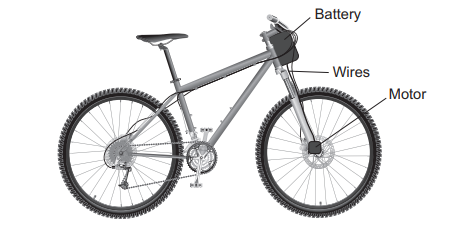
Figure 1 shows a converted bicycle.
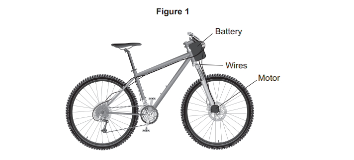
Diagram of a mountain bike showing an electric conversion kit: battery on the handlebars, wires along the frame, and a motor on the front wheel hub.

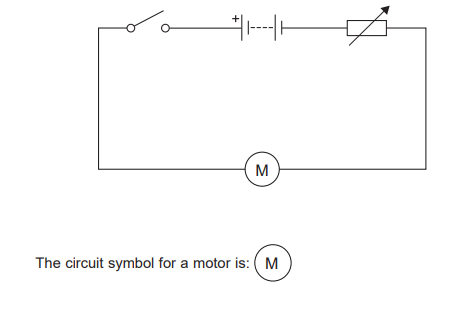
Figure 2 shows the circuit diagram for the bicycle.
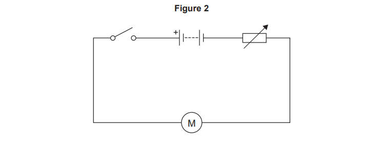
Circuit diagram showing a battery, switch, variable resistor and motor connected in series, with arrows indicating adjustable resistance to control motor speed

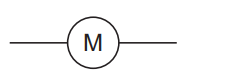
The circuit symbol for a motor is: M

The switch is used to turn the motor on or off.

The variable resistor is used to change the speed of the motor.

Complete the sentences.

Choose answers from the box.

decreases

stays the same

increases

When the resistance of the variable resistor decreases, the potential difference across the battery _________ .

When the resistance of the variable resistor decreases, the current in the circuit _________ .

The speed of the motor increases when the resistance of the variable resistor __________ .

1b
Sme Calculator
2 marks

The potential difference across the motor is 36 V.

The power output of the motor is 252 W.

Calculate the current in the motor.

Use the equation:

current=powerpotential difference

1c
1 mark

The bicycle battery can be recharged using the mains electricity supply.

A battery supplies direct current.

Mains electricity supplies alternating current.

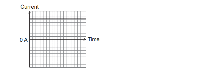
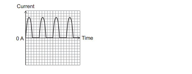
Which graph shows an alternating current?
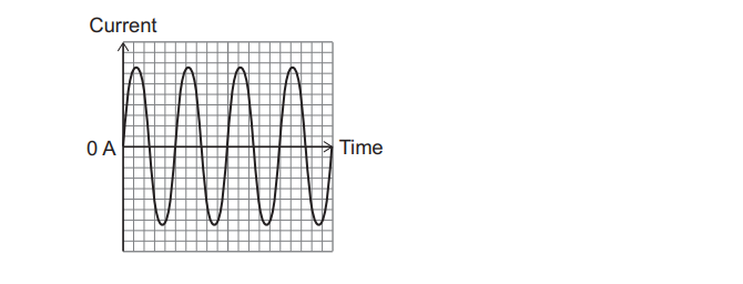
  • Graph of alternating current against time, showing a sinusoidal waveform oscillating above and below the 0 ampere line on a square grid.
  • Blank grid of a current–time graph, with vertical axis labelled “Current”, horizontal axis labelled “Time”, and a bold horizontal line marked 0 A across the middle
  • Graph of current against time showing repeated positive pulses above 0 A, each rising and falling sharply, with no negative current values.
1d
1 mark

A diode is used to change the alternating current to a direct current.

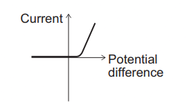
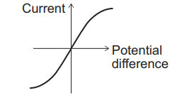
Which graph shows how the current in a diode varies with potential difference?
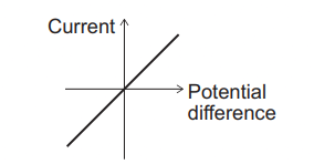
  • Graph of current versus potential difference showing a straight line through the origin, indicating current is directly proportional to potential difference.
  • IV graph showing current versus potential difference with a horizontal line at low voltage then a sharp upward slope, indicating a threshold before current increases
  • Graph of current against potential difference showing an S-shaped non-linear curve, indicating changing resistance with increasing voltage
1e
Sme Calculator
3 marks

The mean charging current from the mains is 5.0 A for 7200 seconds.

Calculate the charge flow to the battery.

Use the equation:

charge flow=current×time

Choose the unit from the box.

amps

coulombs

ohms

volts

1f
Sme Calculator
2 marks

Calculate the work done in charging the battery when the power input is 1150 W for 7200 seconds.

Use the equation:

work done=power×time

2a
1 mark

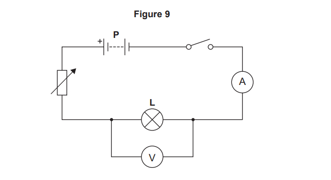
Two students investigated how the current in filament lamp L varied with the potential difference across the lamp.

Figure 9 shows the circuit used.

Circuit diagram showing cell P, variable resistor, switch, ammeter in series with lamp L, and voltmeter connected in parallel across the lamp

What is component P?
  • Battery

  • Cell

  • Fuse

2b
1 mark

The resistance of the variable resistor is increased.

How does increasing the resistance of the variable resistor affect the reading on the ammeter?

  • The ammeter reading decreases.

  • The ammeter reading stays the same.

  • The ammeter reading increases.

2c
2 marks

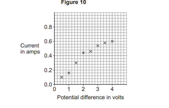
Figure 10 shows the results.

Scatter graph titled Figure 10 showing current increasing roughly linearly from 0 to 0.6 amps as potential difference rises from 0 to 4 volts.

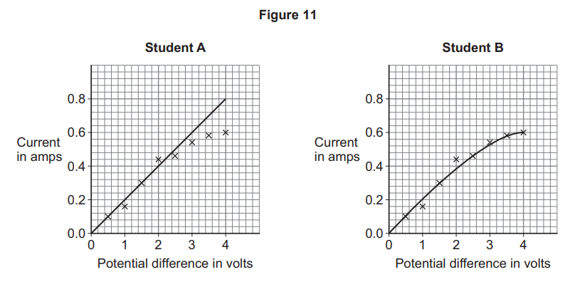
Figure 11 shows the line of best fit drawn by each student.

Two graphs compare Student A’s linear current–voltage relationship to Student B’s curved graph, both showing current rising as potential difference increases.

Explain why student B's line of best fit is correct.

2d
1 mark

What type of error will have caused the point at 2 V to be above the line of best fit?

  • A random error

  • A systematic error

  • A zero error

2e
Sme Calculator
2 marks

When the potential difference across the filament lamp is 1.5 V, the current in the lamp is 0.3 A.

Calculate the resistance of the filament lamp.

Use the equation:

resistance=potential differencecurrent

2f
3 marks

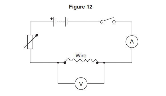
The students investigated how the length of a wire affects the resistance of the wire.

Figure 12 shows the circuit used.

The temperature of the wire was kept constant.

Circuit diagram showing cell, variable resistor, switch, ammeter, and a wire section with a voltmeter connected across it to measure potential difference.

Identify the variables in the investigation.

Tick one box in each row.

Variable

Control variable

Dependent variable

Independent variable

Length of the wire

Resistance of the wire

Temperature of the wire

3a
1 mark

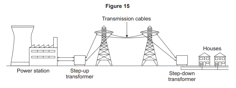
Figure 15 shows how the National Grid connects a power station to houses.

Diagram showing electricity from a power station through a step-up transformer, pylons with transmission cables, then a step-down transformer to houses

The National Grid transfers electrical power efficiently from power stations to houses.

The step-down transformer supplies mains electricity to the houses.

Complete the sentence.

Choose the answer from the box.

charge

current

potential difference

resistance

The step-down transformer decreases the -------------.

3b
3 marks

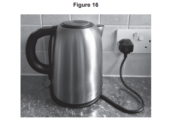
Figure 16 shows an electric kettle plugged into a socket in a house.

Stainless steel electric kettle on a kitchen worktop, plugged into a wall socket with cable trailing across the surface

The cable connecting the kettle to the socket is a three-core cable.

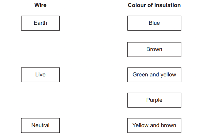
The insulation on each wire is a different colour.

Draw one line from each wire to the colour of insulation.

Matching activity showing three wire types (earth, live, neutral) on the left and five insulation colours (blue, brown, green and yellow, purple, yellow and brown) on the right
3c
1 mark

Use the Physics Equations Sheet to answer this question.

Which equation links charge flow (Q), energy (E) and potential difference (V)?

  • E=QV

  • E=QV2

  • E=Q2V

  • E=QV

3d
Sme Calculator
3 marks

Use the Physics Equations Sheet to answer this question.

The kettle is switched on to heat some water.

The energy transferred to the heating element in the kettle is 260 000 J.

The potential difference across the heating element is 1.3 V.

Calculate the charge flow in the heating element.

4a
1 mark

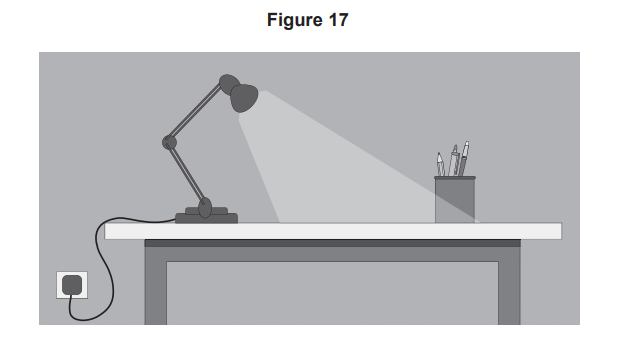
Figure 17 shows a desk lamp connected to the mains electricity supply.

Illustration of a desk with an anglepoise lamp plugged into a wall socket, shining light onto a pot of pencils on the right side of the work surface

The desk lamp is fitted with a high-efficiency LED bulb.

What does ‘high-efficiency’ mean?

  • A large proportion of the total energy input is destroyed.

  • A large proportion of the total energy input is usefully transferred.

  • A large proportion of the total energy input is wasted.

4b
Sme Calculator
2 marks

The output power of the lamp is 2.8 W.

Calculate the energy transferred by the lamp in 60 seconds.

Use the equation:

energy transferred=power×time

4c
4 marks

Mains electricity can be dangerous.

Table 2 shows information about the effects of different electrical supplies on the human body.

Table 2

Effect on the human body

Minimum current needed to cause pain in milliamps

50 Hz ac supply

10 000 Hz ac supply

Mild pain

10

45

Moderate pain

15

65

Severe pain

20

80

ac is alternating current.

Compare the effects on the human body of 50 Hz ac with 10 000 Hz ac.

Use data from Table 2.

5a
3 marks

A normal bicycle can be converted into an electric bicycle.

Figure 9 shows a converted bicycle.

Figure 9

Diagram of an electric bicycle showing labelled battery on the frame bag, wires along the frame, and motor on the rear wheel hub

Figure 10 shows the circuit diagram for the bicycle.

Simple circuit diagram with switch, battery, variable resistor and motor labelled M; below, text states the circuit symbol for a motor is the letter M in a circle

The switch is used to turn the motor on or off.

Explain how the variable resistor is used to control the speed of the motor.

5b
3 marks

The battery can be recharged using the mains electricity supply.

The mains supply is alternating current.

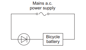
Figure 11 shows a simplified version of the circuit that is used to recharge the battery.

Figure 11

Circuit diagram showing a mains a.c. power supply charging a bicycle battery through a single diode in series.

Explain why charge only passes in one direction through the circuit.

5c
Sme Calculator
5 marks

The mains supply fully recharged the battery in 2 hours.

The mean charging current was 5.0 A.

The resistance of the battery was 0.18 Ω.

Calculate the energy dissipated due to the resistance of the battery in 2 hours.

Use the Physics Equations Sheet.

6a
2 marks

A student carried out an investigation using an electrical circuit.

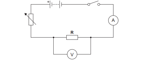
Figure 8 shows the circuit used.

Figure 8

Circuit diagram with battery, switch, variable resistor, fixed resistor R, ammeter in series and voltmeter connected in parallel across resistor R

The student increased the resistance of the variable resistor.

Describe what happened to the potential difference across resistor R and the current in resistor R.

6b
2 marks

The student investigated how the current in resistor R varied with the potential difference across resistor R.

To keep the temperature of resistor R constant, the student opened the switch after taking each reading.

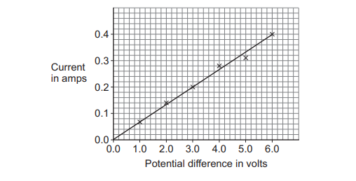
Figure 9 shows the results.

Figure 9

Line graph showing current in amps versus potential difference in volts, with data points forming a straight line from 0,0 to about 0.4 A at 6 V.

Explain what happens to the resistance of resistor R as the potential difference across resistor R increases.

Use information from Figure 9.

6c
2 marks

After the reading was taken at 4.0 V, the student did not open the switch before taking the reading at 5.0 V.

Explain why the current was lower than expected when the 5.0 V reading was taken.

6d
4 marks

The student had more resistors with the same resistance as resistor R.

Describe a method to investigate how the number of resistors in parallel affects the total resistance of the resistors in parallel.

7a
Sme Calculator
3 marks

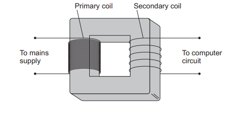
Figure 10 shows a step-down transformer that is part of a circuit inside a computer.

The transformer connects the mains supply to the computer circuit.

Figure 10

Diagram of a transformer with labelled primary coil to mains supply and secondary coil to computer circuit, wound on a rectangular iron core

The potential difference across the primary coil is 230 V.

The potential difference across the secondary coil is 48.0 V.

The current in the primary coil is 2.40 A.

Calculate the current in the secondary coil.

Use the Physics Equations Sheet.

7b
Sme Calculator
3 marks

The current in the primary coil is 2.40 A.

Calculate the time taken for a charge of 288 C to flow past a point in the primary coil.

Use the Physics Equations Sheet.

Give your answer in minutes.

7c
3 marks

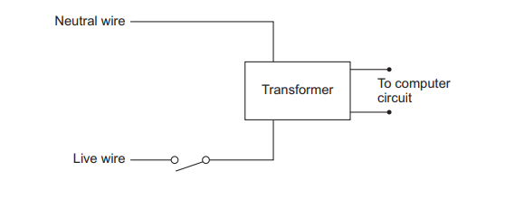
Figure 11 shows the mains electricity circuit for the transformer.

Figure 11

Circuit diagram showing live and neutral mains wires feeding a transformer, with a switch on the live wire and two low-voltage outputs labelled to computer circuit

An electrician replaced a faulty switch connecting the transformer to the mains supply.

The circuit was disconnected from the mains supply to prevent the electrician from receiving an electric shock.

Explain why the electrician could have received a shock if the circuit was connected.

7d
3 marks

Table 2 shows information about the effects of different electrical supplies on the human body.

Table 2

Effect on the human body

Minimum current needed to cause the effect in milliamps

50 Hz ac supply

10 000 Hz ac supply

dc supply

Mild pain

8

46

52

Moderate pain

14

63

64

Severe pain

19

79

75

ac is alternating current.

dc is direct current.

The mains electricity supply in the UK is ac with a frequency of 50 Hz.

Describe why it would be better if the UK mains supply was not 50 Hz ac.

8a
1 mark

A student investigated resistance in a circuit. The student measured:

  • the current in the resistor with an ammeter

  • the potential difference across the resistor with a voltmeter

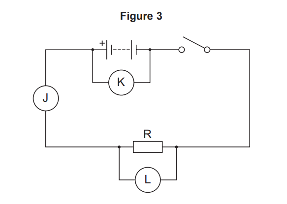
Figure 3 shows a circuit diagram.

Figure 3: simple series circuit with cell, open switch, resistor R, and meters J, K, L placed around the loop for measuring current and voltage

Which letter on Figure 3 shows the correct position for the ammeter to measure the current in the resistor?

Tick (✓) one box.

  • J

  • K

  • L

8b
1 mark

Draw the circuit symbol for a voltmeter in the box .

8c
1 mark

The student changed the number of identical resistors in the circuit.

The student calculated the total resistance of the resistors.

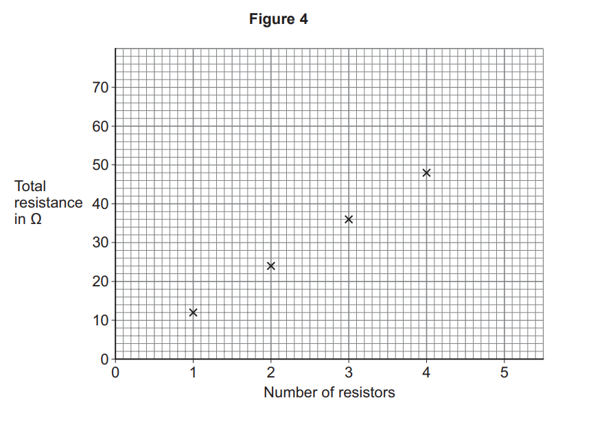
Figure 4 shows the results.

Scatter graph titled Figure 4 showing total resistance in ohms increasing with number of resistors, with plotted points for 1 to 4 resistors.

Draw a line of best fit on Figure 4.

8d
1 mark

Predict the total resistance when 5 resistors were connected in the circuit.

You should extend your line of best fit.

Total resistance = _____________ Ω

8e
2 marks

How were the identical resistors connected in the student’s circuit?

Use Figure 4.

Tick (✓) one box.

  • The resistors were connected in parallel

  • The resistors were connected in series

  • The resistors were connected in series and in parallel

8f
Sme Calculator
2 marks

The potential difference across the battery was 3.0 V.

The maximum current in the circuit in the student’s investigation was 0.25 A.

Calculate the maximum power output of the battery in the student’s investigation.

Use the equation:

power=potential difference×current

Power = W

9a
1 mark

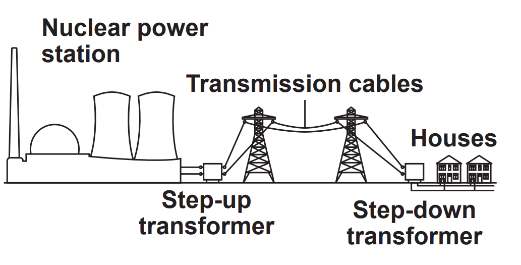
FIGURE 1 shows how the National Grid connects a nuclear power station to houses.

Figure 1

Diagram showing electricity from a nuclear power station passing through a step-up transformer, transmission cables and a step-down transformer to houses

What is ONE advantage of generating electricity using nuclear power?

  • Generating electricity using nuclear power is reliable.

  • Generating electricity using nuclear power produces radioactive waste.

  • Nuclear fuel is non-renewable.

9b
1 mark

The step-up transformer INCREASES the efficiency of power transmission.

How does the step-up transformer affect the potential difference across the transmission cables?

  • The potential difference decreases.

  • The potential difference stays the same.

  • The potential difference increases.

9c
1 mark

How does the step-up transformer affect the current in the transmission cables?

  • The current decreases.

  • The current stays the same.

  • The current increases.

9d
1 mark

How does the step-up transformer affect the energy transferred from the transmission cables to the surroundings?

  • The energy transferred to the surroundings decreases.

  • The energy transferred to the surroundings stays the same.

  • The energy transferred to the surroundings increases.

9e
Sme Calculator
2 marks

The total power input from the nuclear power station to the National Grid is 2400 MW.

efficiency of power transmission = 0.90

Calculate the useful power output in MW.

Use the equation:

useful power output=efficiency×total power input

9f
Sme Calculator
2 marks

TABLE 1 shows the percentage (%) of electricity generated by all the energy resources in the UK on one day in 2022.

TABLE 1

Energy Resource

Percentage (%)

Coal

2

Natural gas

36

Nuclear

X

Renewables

45

Calculate percentage X in TABLE 1.

10a
1 mark

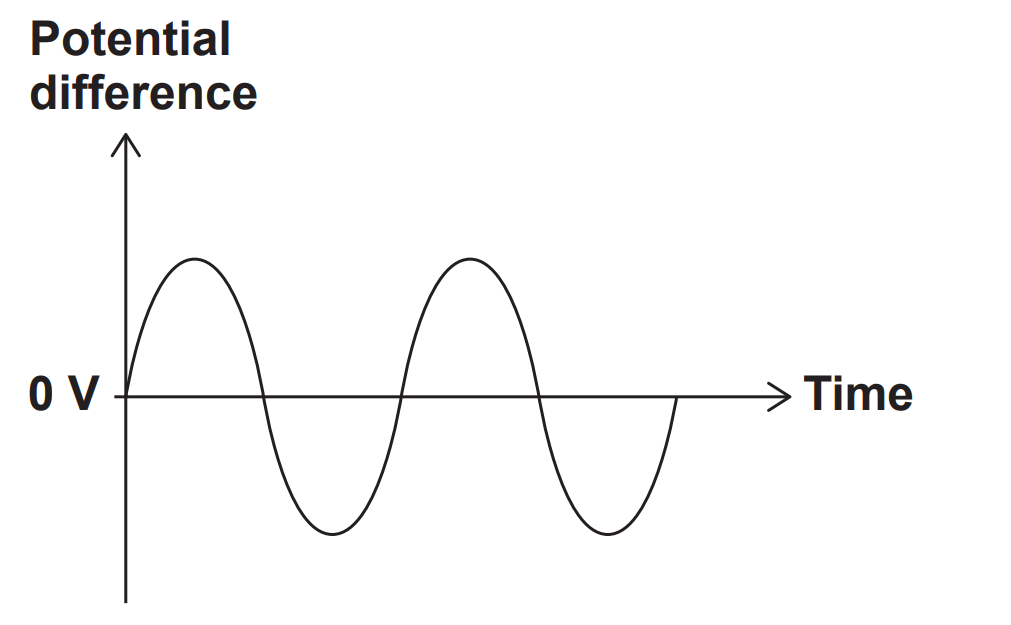
FIGURE 8 shows how the potential difference of the mains electricity supply varies with time.

FIGURE 8

Graph of alternating potential difference versus time, showing a sinusoidal wave oscillating symmetrically above and below the 0 V horizontal axis.

How does FIGURE 8 show that the potential difference is alternating?

  • The potential difference changes direction.

  • The potential difference starts at zero volts.

  • The potential difference varies.

10b
1 mark

What is the potential difference of the mains electricity supply in the UK?

  • 0 volts

  • 50 volts

  • 115 volts

  • 230 volts

10c
2 marks

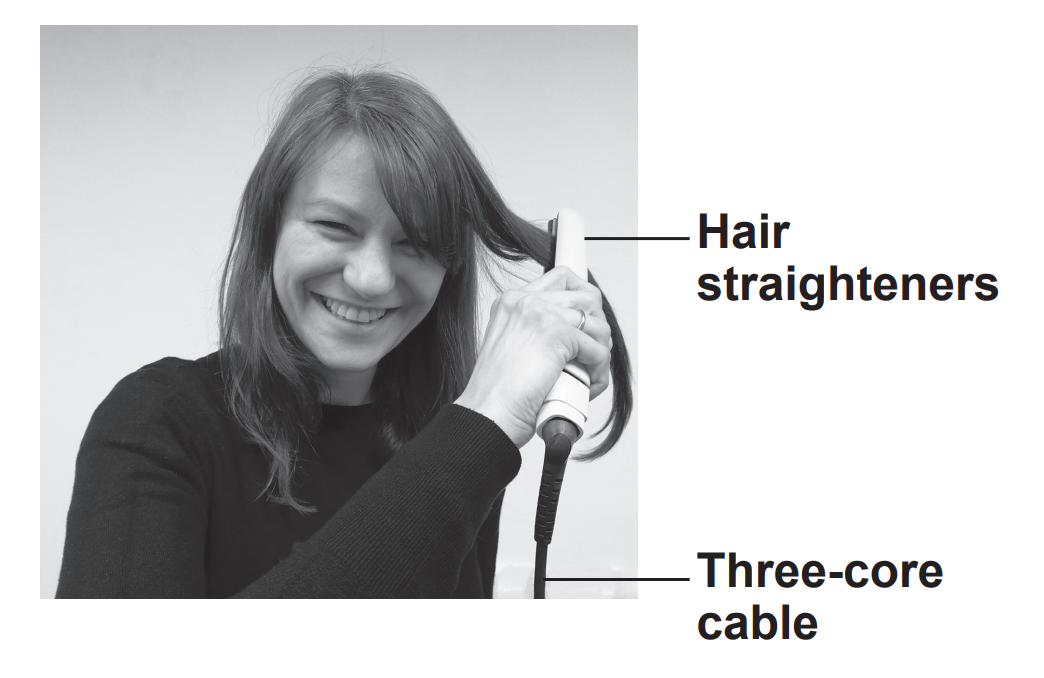
FIGURE 9 shows a student using hair straighteners connected to the mains electricity supply by a three-core cable.

Smiling woman using electric hair straighteners on her hair, with labelled arrows pointing to the straighteners and their three‑core cable

The hair straighteners are connected to the mains electricity supply by a three-core cable.

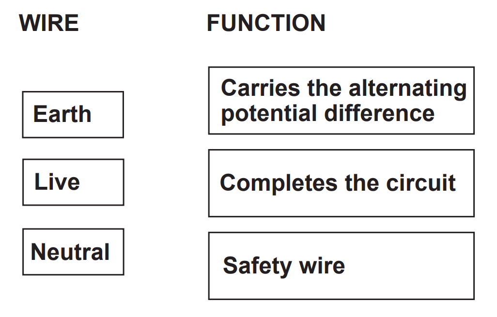
Draw ONE line from the name of each wire to the function of each wire in the cable.

Diagram showing three mains wires: live, neutral and earth, matched to functions: carries alternating potential difference, completes the circuit, and safety wire
10d
2 marks

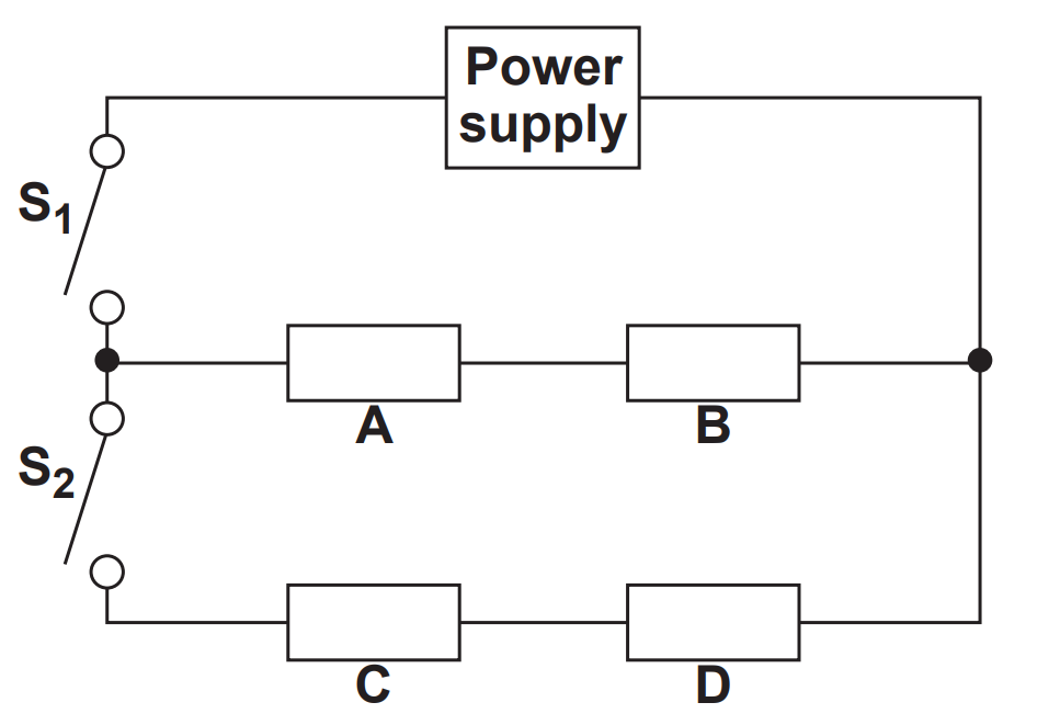
FIGURE 10 shows the circuit diagram for the hair straighteners.

FIGURE 10

Circuit diagram with power supply feeding two switched branches: S1 controls series resistors A and B, S2 controls series resistors C and D in parallel path.

The resistors A, B, C and D represent four heating elements in the hair straighteners.

Complete TABLE 3 to show how switches S1 and S2 are used to switch the heating elements on or off.

The first row of the table has been completed for you.

Switches

Heating Elements ON or OFF?

A and B

C and D

S1 open and S2 open

off

off

S1 closed and S2 open

?

?

S1 closed and S2 closed

?

?

10e
1 mark

Use the Physics Equations Sheet to answer this question.

Write down the equation which links energy transferred (E), power (P) and time (t).

10f
Sme Calculator
3 marks

When the hair straighteners are switched off, the heating elements take 20 minutes to cool to room temperature.

The mean power transfer to the surroundings during this time is 12 W.

Calculate the energy transferred to the surroundings by the heating elements in 20 minutes.

11a
6 marks

A solar cell generates a potential difference when light shines on its surface.

A student investigated how the potential difference varied with the light intensity at the surface of the solar cell.

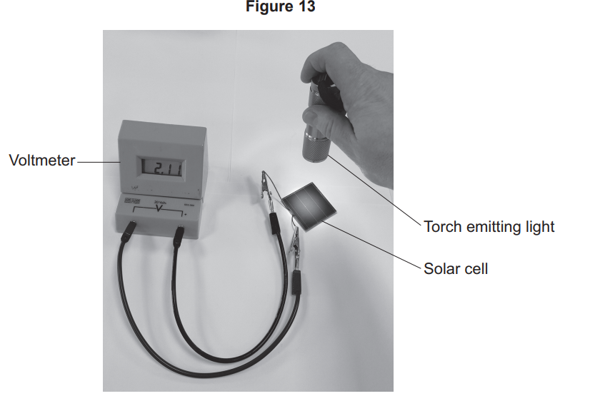
Figure 13 shows some of the equipment used by the student.

Hand shining a torch onto a small solar cell connected by leads to a voltmeter, demonstrating light producing a voltage reading of about 2.1 volts

The voltmeter displayed the potential difference generated by the solar cell.

The student varied the light intensity by changing the height of the torch above the solar cell.

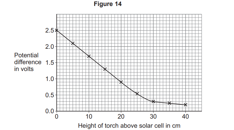
Figure 14 shows the results.

Line graph showing potential difference from 2.5 V to 0 V decreasing as torch height above a solar cell increases from 0 to 40 cm, with plotted data points

Describe a method the student could have used to obtain the results shown in Figure 14.

11b
1 mark

The circuit symbol for a solar cell is

Circuit symbol of a light-dependent resistor or photoresistor, shown as a resistor in a circle with arrows indicating incident light and a positive terminal

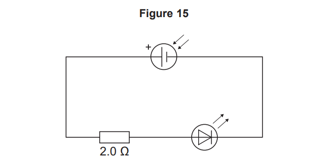
Figure 15 shows the solar cell in a circuit with an LED and a resistor.

Simple series circuit with a cell, a 2.0 ohm resistor and a light‑emitting diode connected in a single loop, current flowing clockwise.

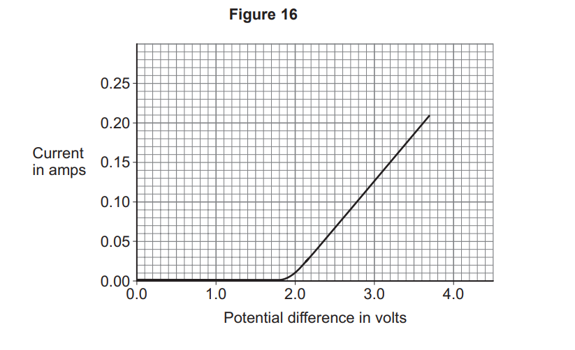
Figure 16 shows how the current in the LED varies with the potential difference across the LED.

Graph of current against potential difference: no current until about 2 V, then current rises linearly to about 0.21 A at 3.8 V.

What is the range of potential difference values for which the LED emits light in Figure 16?

Range of values =_____________ to __________ V

11c
1 mark

Use the Physics Equations Sheet to answer questions 09.3 and 09.4.

Which equation links current (I), potential difference (V) and resistance (R)?

Tick (✓) one box.

  • V=IR

  • V=I2R

  • V=IR2

  • V=IR

11d
Sme Calculator
4 marks

Determine the resistance of the LED when the potential difference across the LED is 2.7 V.

Use Figure 16.

Resistance = _____________ Ω

11e
2 marks

Describe how the resistance of the LED varies as the p.d. increases from 0 V to 3.7 V.

Use data from Figure 16.

12a
2 marks

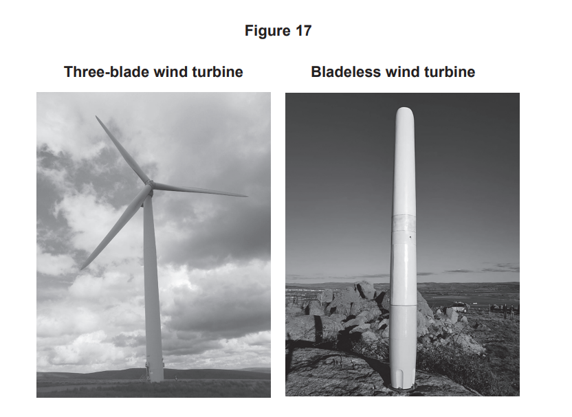
Figure 17 shows two different designs of wind turbine.

Side‑by‑side photos comparing a tall three‑blade wind turbine and a slim bladeless wind turbine standing outdoors under cloudy skies

To generate electricity, the three-blade wind turbine rotates about an axis.

To generate electricity, the bladeless wind turbine oscillates from side to side.

Table 6 gives information about the two designs.

Table 6

Feature

Three-blade turbine

Bladeless turbine

Lubrication needed

Yes

No

Maintenance costs

High

Low

Noise level

High

Low

Power output

High

Low

Risk to flying birds

Yes

No

Which feature of the three-blade turbine is an advantage compared with the bladeless turbine?

Use Table 6.

Give a reason for your answer.

Feature ___________________________________________________

Reason ___________________________________________________

12b
2 marks

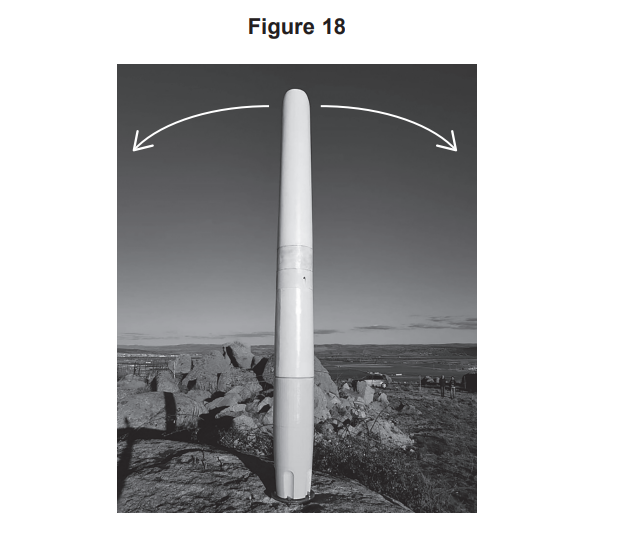
To generate electricity, the bladeless wind turbine oscillates from side to side.

Figure 18 shows the direction of the oscillations of the bladeless wind turbine.

Tall, cylindrical antenna on rocky ground beneath open sky, with two curved arrows above it indicating side-to-side rotational movement

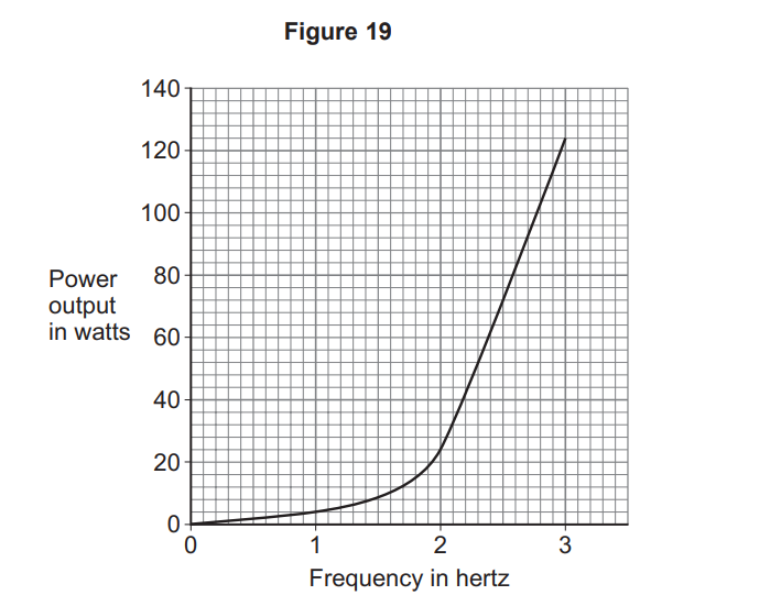
Figure 19 shows how the power output of the bladeless turbine varies with the frequency of the oscillation.

Line graph titled Figure 19 showing power output rising slowly then sharply from 0–3.2 hertz, reaching about 125 watts at 3.2 hertz.

Describe how the power output of the bladeless turbine varies with frequency.

12c
1 mark

The energy from wind turbines can be used to recharge a battery.

Use the Physics Equations Sheet to answer questions 10.3 and 10.4.

Which equation links charge flow (Q), current (I) and time (t)?

Tick (✓) one box.

  • Q=It

  • Q=It2

  • Q=I2t

  • Q=It

12d
Sme Calculator
4 marks

To fully recharge the battery, a charge of 216 000 C needs to flow through the battery.

The current in the battery is 5.0 A.

Calculate the time taken to fully recharge the battery.

Give the unit.

Time taken = _____________Unit _____________

13a
1 mark

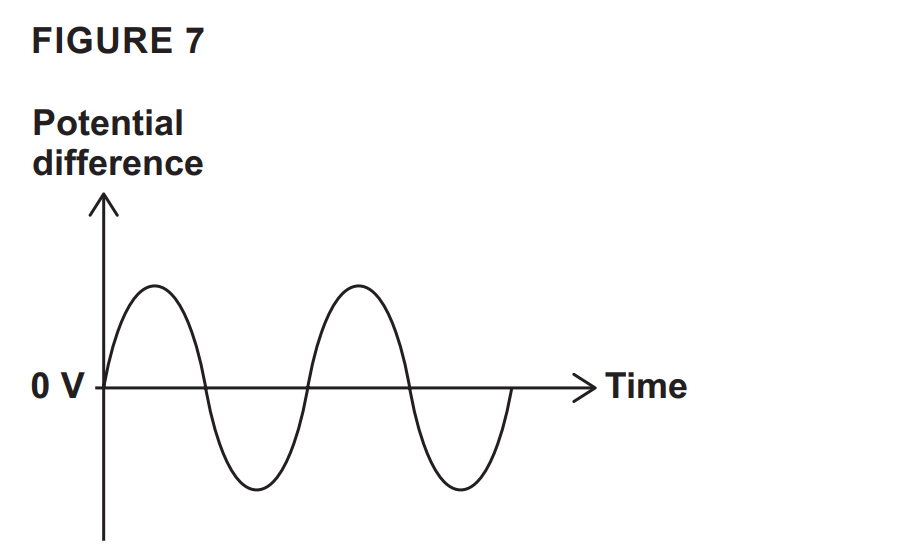
FIGURE 7 shows how the potential difference of the mains electricity supply varies with time.

Graph of alternating potential difference versus time, showing a sinusoidal wave oscillating above and below the 0 V horizontal axis.

How does FIGURE 7 show that the potential difference is alternating? [1 mark]

13b
1 mark

What is the potential difference of the mains electricity supply in the UK? [1 mark]

Mains potential difference =________________ V

13c
1 mark

What is the frequency of the mains electricity supply in the UK? [1 mark]

Mains frequency = _____________________ Hz

13d
1 mark

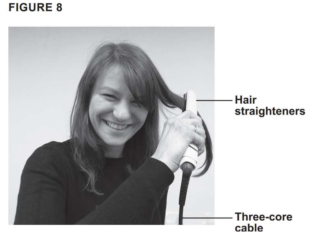
FIGURE 8 shows a student using hair straighteners.

The hair straighteners contain heating elements which transfer thermal energy to the hair.

Smiling woman using electric hair straighteners on her hair, with labelled arrows pointing to the straighteners and their three-core cable

The hair straighteners are connected to the mains electricity supply by a three-core cable.

What is the function of the earth wire in the three-core cable?

Tick (✓) ONE box. [1 mark]

  • To carry the alternating potential difference from the supply

  • To complete the circuit

  • To stop the appliance becoming live

13e
3 marks

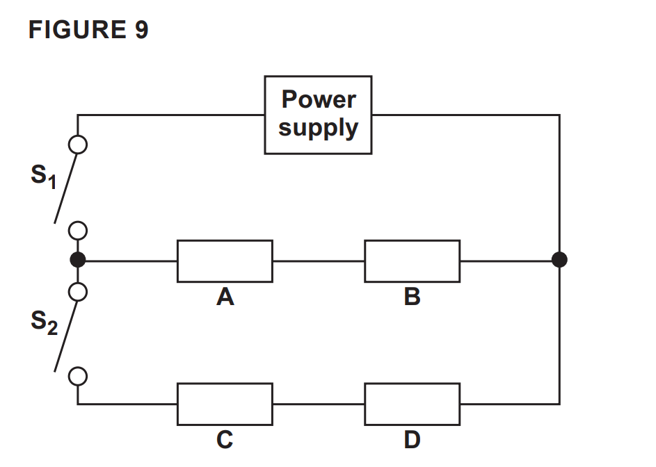
FIGURE 9 shows the circuit diagram for the hair straighteners.

Circuit diagram with power supply and two switches S1, S2 controlling two parallel branches containing components A–B (upper) and C–D (lower).

The resistors A, B, C and D represent four identical heating elements in the hair straighteners.

The hair straighteners have two power settings.

Describe how using S1 and S2 controls the power output of the hair straighteners. [3 marks]

13f
Sme Calculator
4 marks

When the hair straighteners are switched off, the heating elements cool down to room temperature.

The energy transferred to the surroundings is 14.4 kJ.

The mean power transfer to the surroundings is 12 W.

Calculate the time taken for the heating elements to reach room temperature.

Use the Physics Equations Sheet. [4 marks]

Time = ________________________ s

14a
2 marks

A hairdryer contains a heating element and a motor.

The motor is connected to a fan.

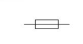
The symbol for the heating element is shown below.

Simple rectangular block symbol with a horizontal line entering from the left and exiting on the right, representing a generic process or component

The symbol for the motor is M is shown below.

Electrical schematic symbol of a motor, shown as a circle with the letter M in the centre and horizontal connection lines on both sides

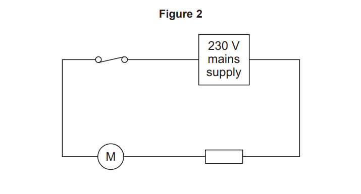
Figure 2 shows part of the electrical circuit inside the hairdryer.

Simple circuit diagram showing 230 V mains supply, a switch, a motor labelled M and a resistor connected in series in a single closed loop

How does the current in the motor compare with the current in the heating element?

Give a reason for your answer.

Tick (✓) one box.

  • The current is greater in the motor.

  • The current in both components is the same.

  • The current is less in the motor.

14b
2 marks

The potential difference across the motor is 20 V.

What is the potential difference across the heating element?

Give a reason for your answer.

Tick (✓) one box.

  • 20 V

  • 50 V

  • 210 V

  • 230 V

14c
Sme Calculator
2 marks

The hairdryer transfers 460 000 J of energy in 250 seconds.

Calculate the power of the hairdryer.

Use the equation:

power = energy transferred / time

14d
Sme Calculator
2 marks

The current in the hairdryer is 8.0 A.

Calculate the time taken for 1200 C of charge to flow past a point in the hairdryer circuit.

Use the equation:

time = charge flowcurrent

14e
1 mark

The hairdryer is connected to the mains electricity supply.

What is the frequency of the UK mains electricity supply?

Tick (✓) one box.

  • 50 Hz

  • 60 Hz

  • 100 Hz

  • 230 Hz

15
Sme Calculator
3 marks

The power output of the generator in the wind turbine is 144 000 W.

The potential difference across the generator is 960 V.

Calculate the current in the generator.

Current = _______________________ A

Use the Physics Equations Sheet.

16a
1 mark

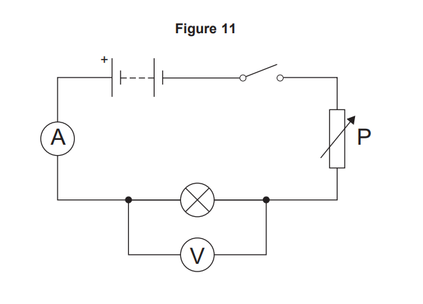
A student investigated how the current in a filament lamp varies with the potential difference across the filament lamp.

Figure 11 shows the circuit used.

Circuit diagram with battery, switch, variable resistor P, lamp in series and ammeter, with a voltmeter connected in parallel across the lamp terminals

What is component P?

Tick (✓) one box.

  • A battery

  • A variable resistor

  • An open switch

16b
4 marks

The student measured different values of potential difference and the corresponding values of current for the filament lamp.

Describe how the student could use the circuit in Figure 11 to make these measurements.

16c
1 mark

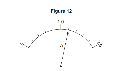
Figure 12 shows the reading on the ammeter at one point in the investigation.

Figure 12: semicircular meter scale from 0 to 2.0, labelled A, with needle pointing close to the 1.0 mark near the centre

What is the reading on the ammeter?

Ammeter reading = _______________ A

16d
3 marks

The student repeated the investigation for two other components.

The student plotted a graph of current against potential difference for each component.

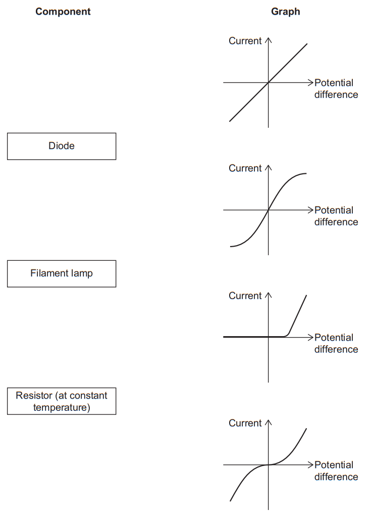
Draw one line from each component to the correct graph.

Table matching components to I–V graphs: diode, filament lamp and fixed resistor, with straight, S-shaped and threshold curves of current vs potential difference.
17a
1 mark

A student investigated how the resistance of a wire varies with the length of the wire.

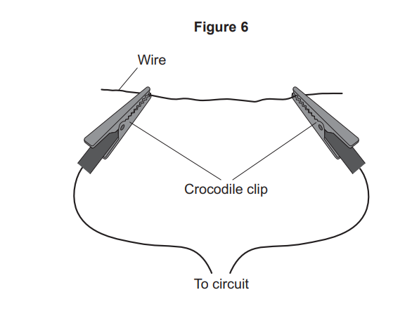
Figure 6 shows how the student connected the wire to a circuit.

Diagram of a wire with a crocodile clip on each end, labelled to show the clips and wires connecting from the wire to an electrical circuit.

Figure 6: A length of wire stretched between two crocodile clips that are connected to the rest of the circuit.

Which piece of equipment should the student use to measure the length of wire between the crocodile clips?

17b
1 mark

The student used readings from the circuit to calculate the resistance of the wire at different lengths.

Figure 7 shows the results.

Figure 7: Resistance (Ω) on the y-axis (0 to 25) and Length of wire (cm) on the x-axis (0 to 100). The data points lie approximately on a straight line through the origin.

Draw a line of best fit on Figure 7.

17c
1 mark

A 100 cm length of wire is placed between the crocodile clips.

Predict the resistance of the 100 cm length of wire.

Use Figure 7.

17d
2 marks

Describe how the results on Figure 7 show that resistance is directly proportional to length.

17e
1 mark

The student switched the circuit off between readings.

Another student did the same investigation but did not switch the circuit off between readings.

What would happen to the temperature of the wire if the circuit was not switched off between readings?

17f
1 mark

What would happen to the resistance of the wire if the circuit was not switched off between the readings?

17g
1 mark

When the student switched the circuit off the ammeter reading was 0.02 A.

What type of error caused the ammeter reading to be 0.02 A?

Tick (✓) one box.

  • A human error

  • A random error

  • A zero error

18a
4 marks

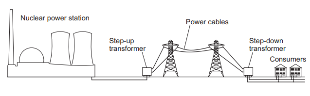
Figure 3 shows how the National Grid links a nuclear power station to consumers.

Figure 3

Diagram showing electricity from a nuclear power station passing through a step-up transformer, pylons and power cables, then a step-down transformer to homes.

Explain why step-up transformers are used in the National Grid.

18b
2 marks

Explain why step-down transformers are used in the National Grid.

18c
Sme Calculator
4 marks

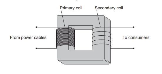
Figure 4 shows a transformer.

Figure 4

Diagram of a transformer showing a rectangular iron core with a primary coil linked to power cables and a secondary coil supplying electricity to consumers

The potential difference across the primary coil is 345 kV.

The potential difference across the secondary coil is 230 V.

The current in the primary coil is 0.060 A.

Calculate the current in the secondary coil.

Use the Physics Equations Sheet.

19a
Sme Calculator
4 marks

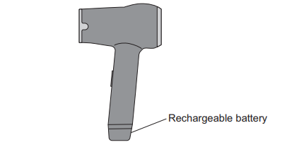
A cordless hairdryer contains a heating element and a fan.

The hairdryer is powered by a rechargeable battery.

Figure 10 shows the cordless hairdryer.

Figure 10

Diagram of a handheld device with a vertical grip, highlighting the lower section of the handle labelled as the rechargeable battery

The power output of the heating element is 0.24 kW when the potential difference across the heating element is 16 V.

Calculate the current in the heating element.

Use the Physics Equations Sheet.

19b
Sme Calculator
6 marks

The battery of the hairdryer can be recharged from 0 to 100% in 6.0 hours.

The power input to the battery is 18 W.

The potential difference across the battery is 24 V.

Calculate the charge flow through the battery in 6.0 hours.

Use the Physics Equations Sheet.

20a
1 mark

A thermistor is an electrical component.

What is the circuit symbol for a thermistor?

Tick (✓) one box.

  • Simple electrical circuit symbol showing a rectangle centred on a horizontal line, representing a resistor or similar component on a schematic diagram
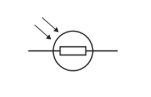
  • Circuit diagram symbol of a light-dependent resistor, with arrows indicating incoming light affecting the enclosed resistor within a circle
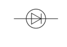
  • Circuit symbol of a diode inside a circle, with a triangle pointing to a vertical line on a horizontal wire, representing current flow in one direction
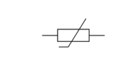
  • Simple electronic circuit symbol showing a variable resistor: a rectangle with a diagonal line through it and straight leads extending left and right
20b
1 mark

A student investigated how the resistance of a thermistor varies with temperature.

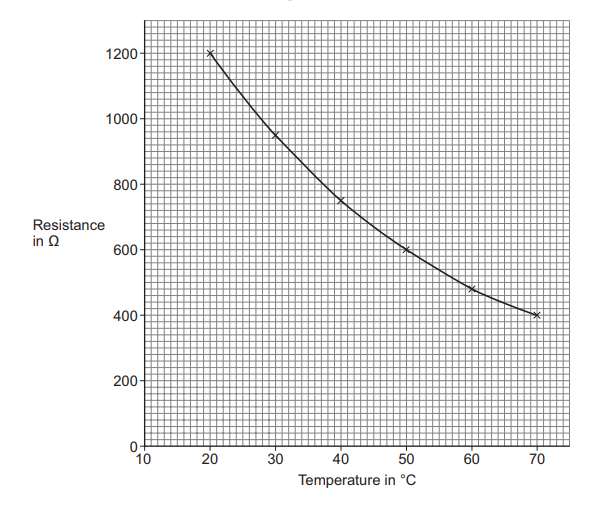
Figure 7 shows the results.

Figure 7

Graph of a thermistor showing resistance decreasing non-linearly from about 1200 Ω at 20°C to 400 Ω at 70°C, with labelled axes for resistance and temperature.

Suggest why the student was not able to take measurements at temperatures below 20 °C.

20c
6 marks

The student used an ammeter and a voltmeter to take measurements to determine the resistance of the thermistor.

Describe a method the student could have used to obtain the results shown in Figure 7.

20d
1 mark

Use the Physics Equations Sheet to answer this question.

Write down the equation which links current (I), potential difference (V) and resistance (R).

20e
Sme Calculator
4 marks

The potential difference across the thermistor was 6.0 V.

Determine the current in the thermistor when the temperature of the thermistor was 40 °C.

Use Figure 7.

21a
4 marks

A student investigated electrical circuits.

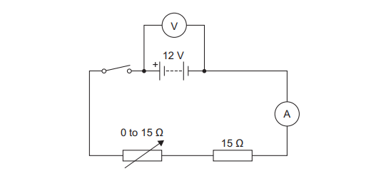
Figure 13 shows a circuit the student made.

Figure 13

A 12 V battery connected in series with: an ammeter (A), a variable resistor (0 to 15 Ω), and a fixed 15 Ω resistor. A voltmeter (V) is connected across the battery.

The student increased the resistance of the variable resistor from 0 to 15 Ω.

Explain what happened to the readings on the voltmeter and ammeter as the resistance was increased.

21b
3 marks

The student changed the position of the voltmeter.

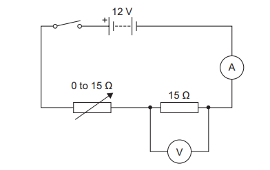
Figure 14 shows the new circuit.

Figure 14

Same 12 V battery, ammeter (A), variable resistor (0 to 15 Ω), and fixed 15 Ω resistor in series. The voltmeter (V) is now connected across the fixed 15 Ω resistor.

The student connected the voltmeter across the 15 Ω fixed resistor.

The student used the variable resistor to vary the potential difference across the fixed resistor.

The potential difference across the fixed resistor can only be varied between 6 V and 12 V using the circuit in Figure 14.

Explain why.

21c
1 mark

Give one way the student could vary the potential difference across the fixed resistor below 6 V.

22a
1 mark

We use mains electricity in our homes.

What is the frequency of the UK mains electricity supply?

Tick (✓) one box.

  • 23 Hz

  • 50 Hz

  • 230 Hz

  • 500 Hz

22b
2 marks

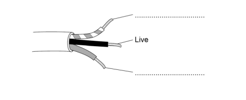
Many appliances in the home use three-core electrical cable.

Figure 7

shows a three-core electrical cable with three wires visible. The middle wire is labelled Live. The top wire and bottom wire have blank label lines pointing to them.

Label the wires in the cable in Figure 7.

Use words from the box.

Box: Earth, Negative, Neutral, Positive

22c
2 marks

The sentences explain how touching the live wire in a cable can cause an electric shock.

Complete the sentences. Use words from the box.

Box: current, force, resistance, potential difference

Touching the live wire causes a large to exist across the body.

This causes a through the body, which results in an electric shock.

22d
Sme Calculator
3 marks

A heater has a power rating of 2500 W.

The heater is turned on for 180 seconds.

Calculate the energy transferred by the heater.

Use the equation:

energy transferred=power×time

Give your answer in kilojoules (kJ).

Energy transferred = kJ

22e
1 mark

Write down the equation that links charge flow, energy transferred and potential difference.

22f
Sme Calculator
3 marks

The mains electricity supply is at 230 V.

A different heater transfers 4200 J of energy.

Calculate the charge flow through the heater.

Charge flow = C

23
Sme Calculator
5 marks

In an electrolysis cell the current is 1.5 × 10⁵ A, at a potential difference of 4 V.

Calculate the energy transferred by the electrolysis cell in 24 hours.

Energy transferred = J

24a
1 mark

An electric current is a flow of electrical charge through a circuit.

Complete the sentence. Use a word from the box.

atoms

electrons

ions

molecules

Metals are good conductors of electricity because electrical charge is transferred by delocalised ---------------------.

24b
3 marks

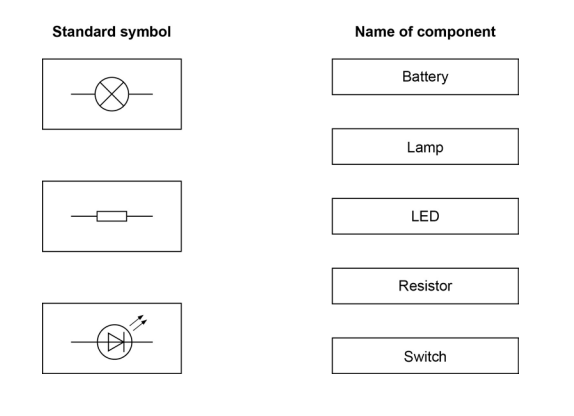
Draw one line from each symbol to the name of the component.

Worksheet showing three circuit symbols on the left and a list of five component names on the right: Battery, Lamp, LED, Resistor and Switch
24c
Sme Calculator
4 marks

Table 2 shows information about some electrical appliances.

Table 2

Electrical appliance

Power in watts

Hairdryer

1500

Kettle

2500

Electric hob

3000

Television

360

A student plugs all four of the appliances into one multi-way socket.

The mains electricity is 230 V.

The highest safe current in the socket is 30 A.

Explain why it is not safe to use all four appliances at the same time.

In your answer you should:

  • calculate the total power needed

  • use the equation

current=powerpotential difference

to calculate the total current needed.

24d
3 marks

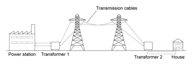
Figure 8 shows how electrical power is transferred from power stations to consumers using the National Grid.

Figure 8

shows how electrical power is transferred from power stations to consumers using the National Grid (power station → Transformer 1 → transmission cables → Transformer 2 → homes/consumers).

Transformer 1 is a step-up transformer.

Explain why step-up transformers are used in the National Grid.

24e
1 mark

What is the purpose of Transformer 2?

25a
4 marks

A student is investigating some electrical components.

Describe how the student could set up a circuit to find the resistance of a lamp.

You should include a circuit diagram in your answer.

25b
2 marks

The student is given an electrical component in a sealed box.

She has to find out what the electrical component is by experiment.

The student records the current and the potential difference for the component.

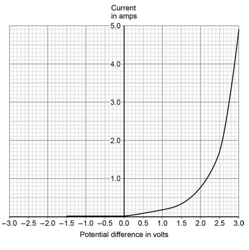
Her results are shown in Figure 6 .

Figure 6

(a graph of current in A on the y-axis against potential difference in V on the x-axis; the curve is flat at zero current for negative p.d., then rises steeply for positive p.d. above ~0.7 V — the typical I–V characteristic of a diode).

Explain how the student could know that the electrical component in the sealed box is not an ohmic conductor.

25c
3 marks

What is the electrical component in the sealed box?

Explain your answer.

Component:

Explanation:

25d
Sme Calculator
4 marks

Use the graph (Figure 6) to determine the resistance of the component at 2.3 V.

Resistance = Ω

26a
2 marks

A student used electrical circuits to investigate the relationship between resistance, potential difference and current.

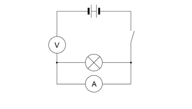
Figure 8 shows how the student connects the first circuit he set up.

Figure 8

The circuit shows a cell and a switch in the main loop; the voltmeter is connected in series with the lamp, and the ammeter is connected in parallel across the lamp — i.e. the meters have been put in the wrong places.

The circuit does not work.

Draw the correct circuit.

26b
1 mark

The student then sets up the circuit correctly.

Look at Figure 9.

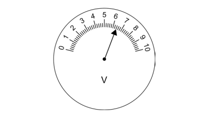
Figure 9

shows the voltmeter (a circular analogue dial scale 0–10 V, with the needle pointing to 6.4).

What is the reading on the voltmeter?

26c
2 marks

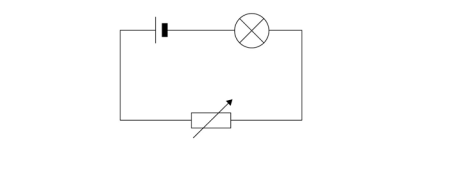
The student then set up a circuit to investigate how resistance affects the brightness of a lamp.

Figure 10 shows the circuit he set up.

Figure 10

(a cell, ammeter, lamp and variable resistor in series).

The student increases the resistance of the variable resistor.

What effect does this have on the brightness of the lamp?

Explain your answer.

26d
1 mark

Write down the equation that links current, potential difference and resistance.

26e
Sme Calculator
3 marks

When the potential difference across the lamp is 3.3 V the current is 0.15 A.

Calculate the resistance of the lamp in the student's experiment.

Resistance = Ω