Required Practical 15: I–V Characteristics (AQA GCSE Combined Science: Synergy: Physical Sciences): Revision Note
Exam code: 8465

Written by: Ashika
Updated on
Required Practical 15: Investigating I–V Characteristics
Aim of the Experiment
The aim of the experiment is to use circuit diagrams to construct appropriate circuits to investigate the I–V characteristics of a variety of circuit elements
These include a fixed resistor at a constant temperature, a lamp and diode
Variables:
Independent variable = Potential difference, V
Dependent variable = Current, I
Control variables:
Potential difference of the power supply
Use of the same equipment eg. wires, diodes
Equipment List
Ammeter
Voltmeter
Variable resistor
Fixed resistor (between 100 Ω and 500 Ω)
Filament lamp
Diode
Voltage Supply
Wires
Resolution of measuring equipment:
Variable resistor = 0.005 Ω
Voltmeter = 0.1 V
Ammeter = 0.01 A
Method

Set up the circuit as shown with the fixed resistor
Vary the voltage across the component by changing the resistance of the variable resistor, using a wide range of voltages (between 8-10 readings). Check the appropriate voltage reading on the voltmeter
For each voltage, record the value of the current from the ammeter 3 times and calculate the average current
Increase the voltage further in steps of 0.5 V and repeat steps 2 and 3
Make sure to switch off the circuit in between readings to prevent heating of the component and wires
Reverse the terminals of the power supply and take readings for the negative voltage (and therefore negative current)
Replace the fixed resistor with the filament lamp, then the diode, repeating the experiment for each
An example of a suitable table might look like this:

Analysis of Results
Plot a graph of average current against voltage (an I–V graph) for each component
If the I–V graph is a straight line, it is an ohmic conductor. This is expected from the fixed resistor
This means it obeys Ohm's Law: V = IR
If the I–V graph is a curve, it is a non-ohmic conductor. This is expected from the filament lamp and diode
Compare the results from the graphs obtained to the known I–V graphs for the resistor, filament lamp and diode. These should look like:
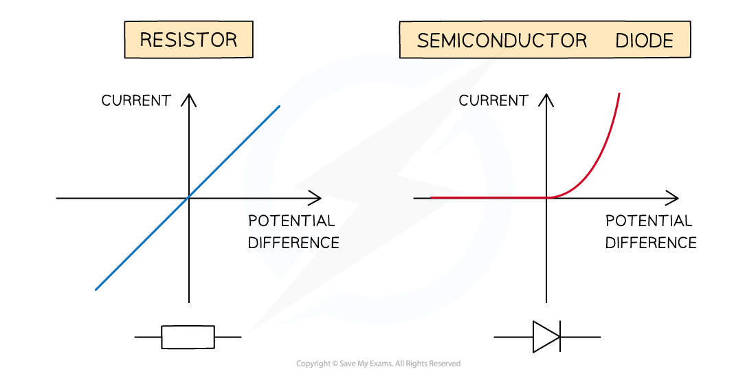
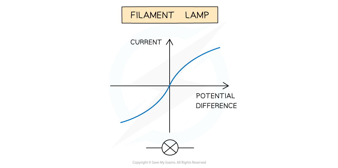
The expected I-V graphs for the resistor, diode and filament lamp
Evaluating the Experiment
Systematic Errors:
The voltmeter and ammeters should start from zero, to avoid zero error in the readings
Random Errors:
In practice, the voltmeter and ammeter will still have some resistance, therefore the voltages and currents displayed may be slightly inaccurate
The temperature of the equipment could affect its resistance. This must be controlled carefully
Taking multiple readings of the current for each component will provide a more accurate result and reduce uncertainties
Safety Considerations
When there is a high current and a thin wire, the wire will become very hot
Make sure never to touch the wire directly when the circuit is switched on
Switch off the power supply right away if burning is smelled
Make sure there are no liquids close to the equipment, as this could damage the electrical equipment
The components will get hot especially at higher voltages
Be careful when handling them - especially the filament lamp
Disconnect the power supply in between readings to avoid the components heating up too much
Examiner Tips and Tricks
In this experiment, the independent variable is the p.d. across the component and the dependent variable is the current flowing through the component. Students often find it confusing to know how to change the p.d. and this depends on the equipment that you use for this investigation. If you use a power pack, then you can easily change the p.d. with a dial, and the experiment is easy to keep track of. However, if you use a battery, or if you use one setting on the power pack, then the p.d. is fixed and you would need to use a variable resistor to change the p.d. It is important that you understand the role of a variable resistor within this experiment, as this is a question that is sometimes asked about in exams!

Unlock more, it's free!
Join the 100,000+ Students that ❤️ Save My Exams
the (exam) results speak for themselves:

Was this revision note helpful?
Build on this topic