Required Practical 16: Investigating Resistance (AQA GCSE Combined Science: Synergy: Physical Sciences): Revision Note
Exam code: 8465

Written by: Ashika
Updated on
Required Practical 16: Investigating Resistance
Equipment List
Equipment | Purpose |
|---|---|
Power supply / battery / cell | Source of potential difference to the circuit |
Wires | Connect all components in the circuits |
Crocodile clips | Connect different lengths of resistance wire |
Ammeter | Measure the current through the circuit |
Voltmeter | Measure the potential difference through the resistors |
Two or more resistors | To measure the resistance of |
Thin resistance wire | To measure the resistance of |
Metre ruler | To measure the length of the resistance wire |
Resolution of measuring equipment:
Metre ruler = 1 mm
Ammeter = 0.01 A
Voltmeter = 0.1 V
Resistance of the Length of a Wire at a Constant Temperature
The aim of this experiment is to investigate how the length of a wire at a constant temperature affects the resistance of electrical circuits
Variables:
Independent variable = Length of resistance wire, L
Dependent variable = Resistance, R
Control variables:
Potential difference of the power supply
Temperature of the wire
Method
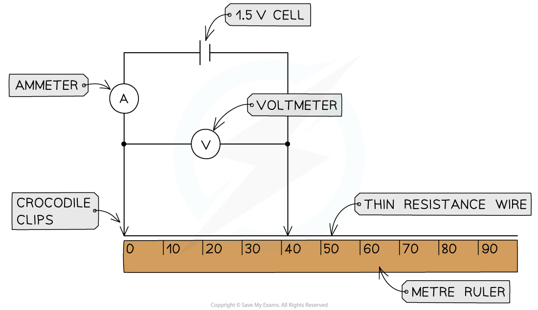
Set up the apparatus by connecting two crocodile clips to the thin resistance wire a distance of 10 cm apart and setting the power supply to 1.5 V
Connect the wire, using the clips, to the rest of the circuit
Record the potential difference from the voltmeter and current from the ammeter
Move the clips in 10 cm intervals further apart
Take new measurements from the voltmeter and ammeter for each length reading
Continue until the crocodile clips are a length of 1 m apart
An example table of results might look like this:

Analysis of Results
Calculate the resistance of each length of wire using the equation:
R =
Where:
R = resistance (Ω)
V = potential difference (V)
I = current (A)
Plot a graph of resistance (on the y-axis) against length (on the x-axis) and draw a line of best fit
An example graph might look like:
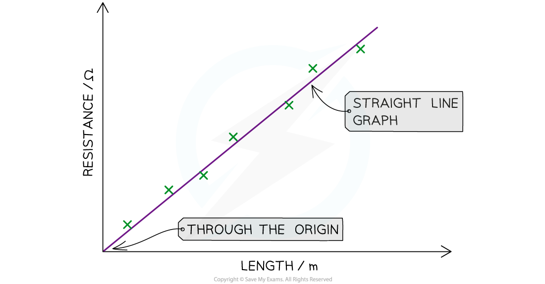
The graph should be a straight line through the origin with a positive correlation
This means that the longer the piece of wire, the higher the resistance
In other words, the resistance is directly proportional to the length of the wire
Examiner Tips and Tricks
This practical is notoriously difficult to obtain valid results from because it is so difficult to control for the heating effect in the wire. Temperature affects resistance, so when the wire heats up, the increased temperature affects the resistance as well as the length of the wire. When this happens, we call it a confounding variable. A variable other than the independent variable has impacted the results, and it is therefore impossible to tell the extent of the effect of the independent variable.
There are ways that you can minimise the impact of a confounding variable (scientists have to work around them all the time in real life situations), and so this often comes up in exam questions.
Only have the circuit connected to take the reading and then disconnect it straight away until you are ready to take the next reading. But at longer and longer lengths of wire, the resistance increases causing more and more heating.
In an ideal scenario, you would wait until the wire had cooled back to room temperature before you took the next reading, but you simply don't have the time to do this in class. However, these are things you could talk about in an exam question if asked for suggestions on improving the investigation.
Combinations of Resistors in Series and Parallel
The aim of this experiment is to investigate how combinations of resistors in series and parallel affect the total resistance in electrical circuits
Variables:
Independent variable = Number of resistors
Dependent variable = Total resistance, R
Control variables:
Potential difference of the power supply
Temperature of the resistors
Method
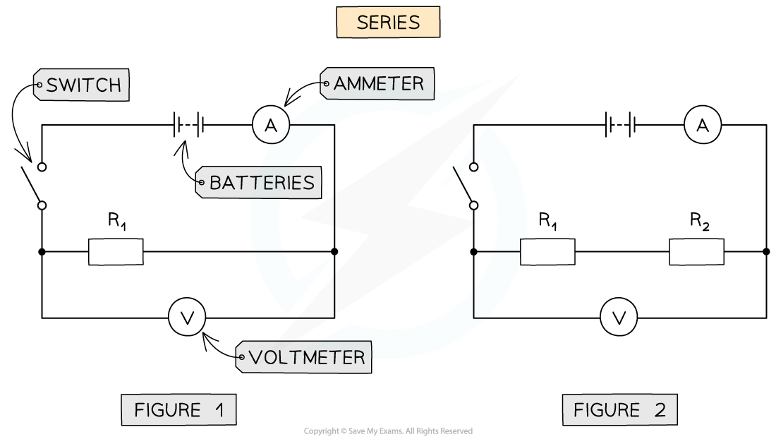
Series and parallel resistor combinations apparatus
Connect the circuit shown in figure 1 with a battery of 4 V, first with one resistor (R1) with the voltmeter connected in parallel and ammeter in series
Close the switch and record the reading on the voltmeter and ammeter
Repeat steps 1 and 2 for just the second resistor (R2)
Open the switch and add connect both R1 and R2 in series as shown in figure 2, connecting the voltmeter in parallel to both resistors
Close the switch and record the new readings on the voltmeter and ammeter
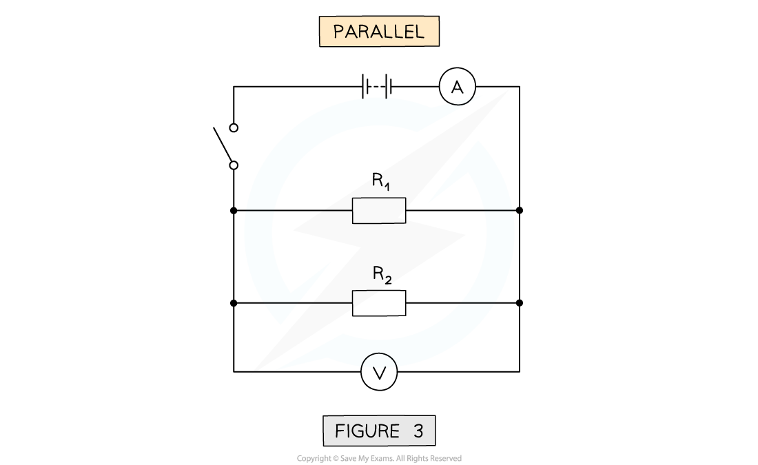
Open the switch and arrange R1 and R2 now in parallel shown in figure 3
Close the switch and record the readings on the voltmeter and ammeter
An example table of results might look like this:

Analysis of Results
Similar to the previous experiment, the resistance for each voltage and current reading is determined by the equation:
R =
The results should show that in series:
The resistance of the combined resistors is equal to the sum of the two individual resistances
This is because the electrons flow through just one path through both resistors, so the current does too
The results should show that in parallel:
The resistance of the combined resistors is less than the sum of the two individual resistances
This is because the electrons are split between the different paths (or 'loops') but the resistors still have the same potential difference across them
Evaluating the Experiment
Systematic Errors:
The first crocodile clip (connected to the circuit, not the wire) must start at 0 on the ruler
Otherwise, this could cause a zero error in your measurements of the length
Both the ammeter and voltmeter should be checked to start from 0
Random Errors:
Only allow small currents to flow through the wire
This keeps the temperature of the wire constant, so it doesn't change its resistance
The current should be switched off between readings so its temperature doesn't change its resistance
Repeat the experiment by reducing the length of the wire 10 cm each time down to a length of 10 cm
Add more resistors in series and parallel to calculate the effect on the combined resistance
Safety Considerations
When there is a high current flowing through a thin wire, the wire will become very hot
Make sure never to touch the wire directly when the circuit is switched on
Switch off the power supply right away if burning is smelled
Make sure there are no liquids close to the equipment, as this could damage the electrical equipment if spilled

Unlock more, it's free!
Join the 100,000+ Students that ❤️ Save My Exams
the (exam) results speak for themselves:

Was this revision note helpful?
Build on this topic