Assembly Language (Cambridge (CIE) A Level Computer Science): Exam Questions

Exam code: 9618

1 hour22 questions
1
5 marks

The following table shows part of the instruction set for a processor. The processor has two registers, the Accumulator (ACC) and the Index Register (IX).

Instruction

Explanation

Opcode

Operand

LDM

#n

Immediate addressing. Load the number n to ACC

LDD

<address>

Direct addressing. Load the contents of the location at the given address to ACC

LDI

<address>

Indirect addressing. The address to be used is at the given address. Load the contents of this second address to ACC

LDX

<address>

Indexed addressing. Form the address from <address> + the contents of the index register. Copy the contents of this calculated address to ACC

LDR

#n

Immediate addressing. Load the number n to IX

ADD

#n/Bn/&n

Add the number n to the ACC

ADD

<address>

Add the contents of the given address to the ACC

SUB

#n/Bn/&n

Subtract the number n from the ACC

SUB

<address>

Subtract the contents of the given address from the ACC

INC

<register>

Add 1 to the contents of the register (ACC or IX)

DEC

<register>

Subtract 1 from the contents of the register (ACC or IX)

<address> can be an absolute or a symbolic address
# denotes a denary number, e.g. #123 B
denotes a binary number, e.g. B01001010
& denotes a hexadecimal number, e.g. &4A

The current contents of memory are shown:

Address

Data

19

25

20

23

21

2

22

4

23

15

24

50

25

22

The current contents of the ACC and IX are shown:

ACC

50

IX

20

Complete the table by writing the content of the ACC and the IX after each set of instructions has run.

Instructions

ACC content

IX content

1

LDM #19
DEC ACC

2

LDD 23
ADD 19

3

LDI 25
INC ACC

4

LDR #21
LDX 2

2
3 marks

The following table shows part of the instruction set for a processor. The processor has two registers, the Accumulator (ACC) and the Index Register (IX).

Instruction

Explanation

Opcode

Operand

LDM

#n

Immediate addressing. Load the number n to ACC

LDD

<address>

Direct addressing. Load the contents of the location at the given address to ACC

LDI

<address>

Indirect addressing. The address to be used is at the given address. Load the contents of this second address to ACC

LDX

<address>

Indexed addressing. Form the address from <address> + the contents of the index register. Copy the contents of this calculated address to ACC

LDR

#n

Immediate addressing. Load the number n to IX

ADD

#n/Bn/&n

Add the number n to the ACC

ADD

<address>

Add the contents of the given address to the ACC

SUB

#n/Bn/&n

Subtract the number n from the ACC

SUB

<address>

Subtract the contents of the given address from the ACC

INC

<register>

Add 1 to the contents of the register (ACC or IX)

DEC

<register>

Subtract 1 from the contents of the register (ACC or IX)

<address> can be an absolute or a symbolic address
# denotes a denary number, e.g. #123 B
denotes a binary number, e.g. B01001010
& denotes a hexadecimal number, e.g. &4A

The current contents of memory are shown:

Address

Data

50

54

51

55

52

50

53

52

54

100

55

25

56

50

The current contents of the ACC and IX are shown:

ACC

50

IX

45

Complete the table by writing the content of the ACC after each program has run.

Instructions

ACC content

1

LDD 50
ADD #4
ADD 54

2

LDI 53
DEC ACC
ADD 56

3

LDM #55
SUB #5

3
4 marks

The following table shows part of the instruction set for a processor. The processor has two registers: the Accumulator (ACC) and an Index Register (IX).

Instruction

Explanation

Opcode

Operand

LDM

#n

Immediate addressing. Load the number n to ACC

LDD

<address>

Direct addressing. Load the contents of the location at the given address to ACC

LDI

<address>

Indirect addressing. The address to be used is at the given address. Load the contents of this second address to ACC

LDX

<address>

Indexed addressing. Form the address from <address> + the contents of the index register. Copy the contents of this calculated address to ACC

LDR

#n

Immediate addressing. Load the number n to IX

ADD

#n/Bn/&n

Add the number n to the ACC

ADD

<address>

Add the contents of the given address to the ACC

SUB

#n/Bn/&n

Subtract the number n from the ACC

SUB

<address>

Subtract the contents of the given address from the ACC

INC

<register>

Add 1 to the contents of the register (ACC or IX)

<address> can be an absolute or a symbolic address
# denotes a denary number, e.g. #123 B
denotes a binary number, e.g. B01001010
& denotes a hexadecimal number, e.g. &4A

The current contents of memory are shown:

Address

Data

19

24

20

2

21

1

22

3

23

5

24

4

25

22

The current contents of the ACC and IX are shown:

ACC

12

IX

1

Complete the table by writing the content of the ACC after each program has run.

Program number

Instructions

ACC content

1

LDD 20
ADD #2

2

LDX 22

3

LDI 25
INC ACC
SUB 22

4

LDD 19
LDM #5
LDM #25

4
4 marks

The following table shows part of the instruction set for a processor. The processor has two registers: the Accumulator (ACC) and an Index Register (IX).

Instruction

Explanation

Opcode

Operand

LDM

#n

Immediate addressing. Load the number n to ACC

LDD

<address>

Direct addressing. Load the contents of the location at the given address to ACC

LDI

<address>

Indirect addressing. The address to be used is at the given address. Load the contents of this second address to ACC

LDX

<address>

Indexed addressing. Form the address from <address> + the contents of the index register. Copy the contents of this calculated address to ACC

LDR

#n

Immediate addressing. Load the number n to IX

ADD

#n/Bn/&n

Add the number n to the ACC

ADD

<address>

Add the contents of the given address to the ACC

SUB

#n/Bn/&n

Subtract the number n from the ACC

SUB

<address>

Subtract the contents of the given address from the ACC

INC

<register>

Add 1 to the contents of the register (ACC or IX)

<address> can be an absolute or a symbolic address
# denotes a denary number, e.g. #123 B
denotes a binary number, e.g. B01001010
& denotes a hexadecimal number, e.g. &4A

The current contents of memory are shown:

Address

Data

10

1

11

3

12

5

13

11

14

10

15

16

16

12

The current contents of the ACC and IX are shown:

ACC

10

IX

0

Complete the table by writing the content of the ACC after each program has run.

Program number

Instructions

ACC content

1

LDI 15
SUB #1

2

LDD 14
ADD 11

3

LDM #11
ADD #3
SUB 16

4

LDR #2
LDX 14
ADD #2

5
4 marks

The following table shows part of the instruction set for a processor. The processor has two registers: the Accumulator (ACC) and an Index Register (IX).

Instruction

Explanation

Opcode

Operand

LDM

#n

Immediate addressing. Load the number n to ACC

LDD

<address>

Direct addressing. Load the contents of the location at the given address to ACC

LDI

<address>

Indirect addressing. The address to be used is at the given address. Load the contents of this second address to ACC

LDX

<address>

Indexed addressing. Form the address from <address> + the contents of the index register. Copy the contents of this calculated address to ACC

LDR

#n

Immediate addressing. Load the number n to IX

ADD

#n/Bn/&n

Add the number n to the ACC

ADD

<address>

Add the contents of the given address to the ACC

SUB

#n/Bn/&n

Subtract the number n from the ACC

SUB

<address>

Subtract the contents of the given address from the ACC

INC

<register>

Add 1 to the contents of the register (ACC or IX)

<address> can be an absolute or a symbolic address
# denotes a denary number, e.g. #123 B
denotes a binary number, e.g. B01001010
& denotes a hexadecimal number, e.g. &4A

The current contents of memory are shown:

Address

Data

48

51

49

6

50

48

51

50

52

49

53

50

54

6

The current contents of the ACC and IX are shown:

ACC

2

IX

50

Complete the table by writing the content of the ACC after each program has run.

Program number

Instructions

ACC content

1

LDM #50
INC ACC
SUB #1

2

LDI 51
ADD 52

3

LDR #2
LDX 50
DEC ACC

4

LDD 52
SUB 54
INC ACC

6a
1 mark

Identify the purpose of the first pass of a two-pass assembler.

6b
6 marks

The following table shows part of the instruction set for a processor. The processor has two registers, the Accumulator (ACC) and the Index Register (IX).

Instruction

Explanation

Opcode

Operand

LDR

#n

Immediate addressing. Load the number n to IX

STO

<address>

Store contents of ACC at the given address

ADD

<address>

Add the contents of the given address to the ACC

INC

<register>

Add 1 to the contents of the register (ACC or IX)

CMP

#n

Compare the contents of ACC with number n

JPE

<address>

Following a compare instruction, jump to <address> if the compare was True

OUT

Output to the screen the character whose ASCII value is stored in ACC

<address> can be an absolute or symbolic address

# denotes a denary number, e.g. #123

(i) Give one example of an instruction that belongs to each of the following instruction groups.

Only use the instructions given in the table. Each instruction must have a suitable operand.

Data movement ...........................

Arithmetic operation ...................

Conditional instruction ................

(3)

(ii) The instruction LDR #2 uses immediate addressing.

Give one similarity and one difference between direct addressing and indexed addressing.

(2)

(iii) Identify one other mode of addressing.

(1)

7a
4 marks

The following table shows part of the instruction set for a processor. The processor has two registers, the Accumulator (ACC) and the Index Register (IX).

Instruction

Explanation

Opcode

Operand

LDD

<address>

Direct addressing. Load the contents of the location at the given address to ACC

LDX

<address>

Indexed addressing. Form the address from <address> + the contents of the index register. Copy the contents of this calculated address to ACC

LDR

#n

Immediate addressing. Load the number n to IX

STO

<address>

Store the contents of ACC at the given address

ADD

#n

Add the denary number n to the ACC

JMP

<address>

Jump to the given address

INC

<register>

Add 1 to the contents of the register (ACC or IX)

CMP

<address>

Compare the contents of ACC with the contents of <address>

CMI

<address>

Indirect addressing. The address to be used is at the given address. Compare the contents of ACC with the contents of this second address

JPE

<address>

Following a compare instruction, jump to <address> if the compare was True

IN

Key in a character and store its ASCII value in ACC

OUT

Output to the screen the character whose ASCII value is stored in ACC

END

Return control to the operating system

<address> can be an absolute or a symbolic address
# denotes a denary number, e.g. #123

The instructions in the processor’s instruction set can be grouped according to their function.

Identify the instruction group for each of the following opcodes.

IN .............................

ADD .........................

JPE ...........................

CMI ...........................

7b
1 mark

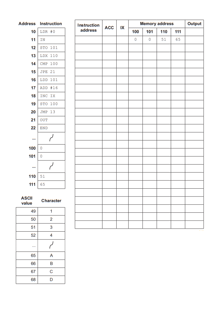
The current contents of main memory and selected values from the ASCII character set are given on page 15.

Trace the program currently in memory using the trace table when the input is ‘1’.

Table with computer instructions, memory addresses, and ASCII values. Includes instruction and output columns, memory values for addresses 100-111.
8
2 marks

Assembly language instructions can use different modes of addressing.

Complete the table by writing the name of the addressing mode that each description describes.

Description

Addressing mode

The address of the data is formed by adding the contents of the Index Register to the operand.

The operand gives an offset. This offset is added to a base address to form the address of the data, so the program still works if it is loaded at a different place in memory.

9
3 marks

The table shows part of the instruction set for a processor. The processor has one general purpose register, the Accumulator (ACC), and an Index Register (IX).

Opcode

Operand

Explanation

LDM

#n

Immediate addressing. Load the number n to ACC

LDD

<address>

Direct addressing. Load the contents of the location at the given address to ACC

LDI

<address>

Indirect addressing. The address to be used is at the given address. Load the contents of this second address to ACC

LDX

<address>

Indexed addressing. Form the address from <address> + the contents of the Index Register. Copy the contents of this calculated address to ACC

<address> can be an absolute or a symbolic address. # denotes a denary number, for example #123.

The current contents of main memory are:

Address

Data

100

104

101

55

102

100

103

12

104

78

105

101

The Index Register (IX) holds the value 2.

Write the single instruction that loads the value 78 into the ACC using each of the addressing modes shown in the table below.

Addressing mode

Instruction

Direct

Indirect

Indexed

10
4 marks

The table shows part of the instruction set for a processor. The processor has one general purpose register, the Accumulator (ACC), and an Index Register (IX).

Opcode

Operand

Explanation

LDM

#n

Immediate addressing. Load the number n to ACC

LDD

<address>

Direct addressing. Load the contents of the location at the given address to ACC

LDI

<address>

Indirect addressing. The address to be used is at the given address. Load the contents of this second address to ACC

LDX

<address>

Indexed addressing. Form the address from <address> + the contents of the Index Register. Copy the contents of this calculated address to ACC

LDR

#n

Immediate addressing. Load the number n to IX

ADD

<address>

Add the contents of the given address to the ACC

<address> can be an absolute or a symbolic address. # denotes a denary number, for example #123.

The current contents of main memory are:

Address

Data

200

204

201

30

202

206

203

201

204

45

205

202

206

18

207

200

208

75

Each program starts with ACC holding 0 and IX holding 3.

Complete the table by writing the contents of the ACC after each program has run.

Program number

Code

ACC contents

1

LDX 201

2

LDI 205

3

LDR #1
LDX 205
ADD 201

4

LDM #207
LDI 207

11
2 marks

A programmer writes a program in assembly language. The processor cannot run this program until it has been translated.

(i) State the name of the software that translates an assembly language program.

(ii) State the name given to the translated program that the processor runs.

12
3 marks

A processor can only run machine code. A programmer chooses to write a program in assembly language instead of writing the machine code directly.

Explain why writing the program in assembly language is easier for the programmer.

13
5 marks

The table shows part of the instruction set for a processor. The processor has one general purpose register, the Accumulator (ACC).

Instruction

Explanation

Opcode

Operand

LDD

<address>

Direct addressing. Load the contents of the location at the given address to ACC

ADD

#n

Add the denary number n to the ACC

STO

<address>

Store the contents of ACC at the given address

END

Return control to the operating system

<address> can be an absolute or a symbolic address
# denotes a denary number, e.g. #123

A programmer writes this assembly language program.

LDD 300
ADD #4
STO 301
END

(i) The program is translated so that the processor can run it. State how many instructions the translated program contains.

(ii) Explain your answer to part (i).

(iii) In its translated form, ADD #4 is one pattern of bits made up of an opcode and an operand. Describe what the processor does with each of these two parts.

14
2 marks

The instructions in a processor's instruction set are placed in groups. Each group contains instructions that carry out a similar kind of task.

The table shows four instructions from one processor's instruction set.

Instruction

Explanation

Opcode

Operand

IN

Key in a character and store its ASCII value in ACC

OUT

Output to the screen the character whose ASCII value is stored in ACC

ADD

#n

Add the denary number n to the ACC

SUB

#n

Subtract the denary number n from the ACC

(i) Name the instruction group that IN and OUT belong to.

(ii) Name the instruction group that ADD and SUB belong to.

15
2 marks

A program written in assembly language is translated into machine code by a two-pass assembler.

State the purpose of the first pass and the purpose of the second pass.

16
3 marks

The table shows part of the instruction set for a processor. The processor has one general purpose register, the Accumulator (ACC), and an Index Register (IX).

Instruction

Explanation

Opcode

Operand

LDD

<address>

Direct addressing. Load the contents of the location at the given address to ACC

STO

<address>

Store the contents of ACC at the given address

ADD

<address>

Add the contents of the given address to the ACC

INC

<register>

Add 1 to the contents of the register (ACC or IX)

CMP

#n

Compare the contents of ACC with number n

JMP

<address>

Jump to the given address

JPE

<address>

Following a compare instruction, jump to the given address if the compare was True

IN

Key in a character and store its ASCII value in ACC

OUT

Output to the screen the character whose ASCII value is stored in ACC

<address> can be an absolute or a symbolic address
# denotes a denary number, e.g. #123

LDD and STO both belong to the data movement group.

Name one other instruction group, describe what the instructions in that group do, and give one example instruction from the table that belongs to it. Your example must include a suitable operand where the instruction needs one.

17
3 marks

A cinema has 250 seats. The memory location at address 300 holds the number of seats that are still free.

A program written in assembly language reads that number and outputs one character to describe the cinema: F if no seats are free, E if every seat is free, and S if some seats are free.

The program is stored in main memory starting at address 50. Each instruction is stored in one memory location.

Address

Label

Instruction

50

LDD 300

51

CMP #0

52

JPE FULL

53

CMP #250

54

JPE EMPTY

55

JMP SOME

56

FULL

LDM #70

57

OUT

58

END

59

EMPTY

LDM #69

60

OUT

61

END

62

SOME

LDM #83

63

OUT

64

END

A two-pass assembler translates this program. During the first pass the assembler builds a symbol table.

Complete the symbol table.

Label

Address

18
4 marks

A program written in assembly language divides the number stored at address 200 by the number stored at address 201, using repeated subtraction. It stores the result at address 202. The value at address 200 is an exact multiple of the value at address 201, and address 202 holds 0 before the program starts.

The program is stored in main memory starting at address 40. Each instruction is stored in one memory location.

Address

Label

Instruction

40

LDD 200

41

AGAIN

CMP #0

42

JPE DONE

43

SUB 201

44

STO 200

45

LDD 202

46

INC ACC

47

STO 202

48

LDD 200

49

JMP AGAIN

50

DONE

END

The program is translated by a two-pass assembler.

Explain why this program cannot be translated into object code in a single pass.

19
5 marks

The table shows part of the instruction set for a processor. The processor has one general purpose register, the Accumulator (ACC).

Instruction

Explanation

Opcode

Operand

LDD

<address>

Direct addressing. Load the contents of the location at the given address to ACC

ADD

#n

Add the denary number n to the ACC

STO

<address>

Store the contents of ACC at the given address

CMP

#n

Compare the contents of ACC with number n

JPN

<address>

Following a compare instruction, jump to the given address if the compare was False

JMP

<address>

Jump to the given address

END

Return control to the operating system

<address> can be an absolute or a symbolic address
# denotes a denary number, e.g. #123

A program is stored in memory at addresses 100 to 105. Address 200 holds the value 3 before the program starts.

100   LDD 200
101   ADD #1
102   STO 200
103   CMP #10
104   JPN 100
105   END

(i) Explain why the instruction JPN 100 at address 104 cannot do its job unless the instruction at address 103 is also present.

(ii) The instruction at address 104 is replaced by JMP 100. Describe the effect this change has when the program runs, and name the instruction group that JMP belongs to.

20
2 marks

The table shows part of the instruction set for a processor. The processor has one general purpose register, the Accumulator (ACC).

Opcode

Operand

Explanation

LDM

#n

Immediate addressing. Load the number n to ACC

LDD

address

Direct addressing. Load the contents of the location at the given address to ACC

ADD

#n

Add the number n to the ACC

SUB

address

Subtract the contents of the given address from the ACC

address can be an absolute or a symbolic address.

# denotes a denary number, for example #123.

The current contents of memory are shown.

Address

Data

60

12

61

9

62

7

63

25

The current content of the ACC is 4. The value 4 is reloaded into the ACC before each program is run.

Complete the table by writing the content of the ACC after each program has run.

Program number

Code

ACC content

1

LDD 62
ADD #5

2

LDM #62
SUB 61

21
3 marks

The table shows part of the instruction set for a processor. The processor has two registers, the Accumulator (ACC) and the Index Register (IX).

Opcode

Operand

Explanation

LDD

address

Direct addressing. Load the contents of the location at the given address to ACC

LDI

address

Indirect addressing. The address to be used is at the given address. Load the contents of this second address to ACC

LDX

address

Indexed addressing. Form the address from the given address + the contents of the Index Register. Copy the contents of this calculated address to ACC

LDR

#n

Immediate addressing. Load the number n to IX

DEC

register

Subtract 1 from the contents of the register (ACC or IX)

address can be an absolute or a symbolic address.

# denotes a denary number, for example #123.

The current contents of memory are shown.

Address

Data

70

74

71

6

72

19

73

71

74

33

75

8

76

41

The current contents of the ACC and the IX are shown.

Register

Content

ACC

5

IX

3

The ACC and the IX are reset to these values before each set of instructions is run.

Complete the table by writing the content of the ACC and the content of the IX after each set of instructions has run.

Set number

Instructions

ACC content

IX content

1

LDR #2
LDX 73

2

LDI 73

3

LDD 72
DEC ACC

22
5 marks

The table shows part of the instruction set for a processor. The processor has one general purpose register, the Accumulator (ACC), and an Index Register (IX).

Opcode

Operand

Explanation

LDR

#n

Immediate addressing. Load the number n to IX

LDX

address

Indexed addressing. Form the address from the given address + the contents of the Index Register. Copy the contents of this calculated address to ACC

CMP

#n

Compare the contents of ACC with number n

JPE

address

Following a compare instruction, jump to the given address if the compare was True

JMP

address

Jump to the given address

INC

register

Add 1 to the contents of the register (ACC or IX)

OUT

Output to the screen the character whose ASCII value is stored in ACC

END

Return control to the operating system

address can be an absolute or a symbolic address.

# denotes a denary number, for example #123.

The current contents of memory are shown. The value 0 at address 153 marks the end of the message.

Address

Data

150

72

151

73

152

33

153

0

The ASCII values used by the program are shown.

ASCII value

Character

72

H

73

I

33

!

The program is shown.

Label

Opcode

Operand

LDR

#0

LOOP

LDX

150

CMP

#0

JPE

FINISH

OUT

INC

IX

JMP

LOOP

FINISH

END

The trace table records what happens on each pass through the loop. The first row has been completed for you.

Complete the trace table.

Pass through the loop

Content of the ACC after LDX 150

Character output during this pass

Content of the IX at the end of this pass

1

72

H

1

2

3

4