Logic Gates & Logic Circuits (Cambridge (CIE) A Level Computer Science): Exam Questions

Exam code: 9618

2 hours30 questions
1
2 marks

A security system has both a floodlight (very bright light) and an audio alarm.

The data from multiple sensors is analysed and used to:

  • turn on the floodlight

  • sound the audio alarm.

Sensors can be used to detect:

  • if doors are open

  • the external daylight level

  • if people are detected within a set distance.

The floodlight (X) and audio alarm (Y) operate according to the following criteria:

Parameter

Description of parameter

Binary value

Condition

A

External daylight level

1

Low

0

High

B

Front door

1

Open

0

Closed

C

Person is within 2 m

1

Detected

0

Not detected

D

Back door

1

Open

0

Closed

E

Security system

1

Switched on

0

Switched off

The floodlight turns on (X = 1) if:

  • the security system is switched on

    and

  • the external daylight level is low

    and

  • a person is detected within 2m.

The audio alarm turns on (Y = 1) if:

  • the security system is switched on

    and

  • one or more doors are open, or a person is detected within 2m.

Write logic expressions for the security system.

2a
2 marks

Complete the truth table for the logic expression:

X = (A XOR B) NAND (A AND (B XOR C))

A

B

C

Workspace

X

0

0

0

0

0

1

0

1

0

0

1

1

1

0

0

1

0

1

1

1

0

1

1

1

2b
2 marks

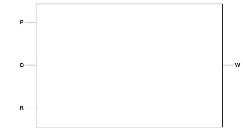
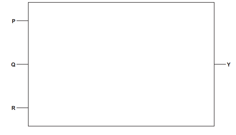
Draw the logic circuit for the logic expression:

W = P NAND ((Q OR NOT R) XOR (P XOR Q))

Rectangular diagram with letters P, Q, R on the left and W on the right, all pointing to the rectangle's edges, labels represent sections or points.
3a
1 mark

Describe the operation of a 2-input XOR gate.

3b
2 marks

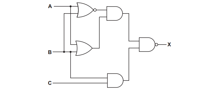
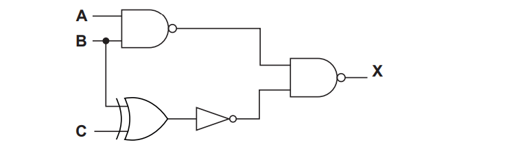
Write the logic expression for the following logic circuit.

Logic gate circuit with A, B, C inputs; connected via AND, OR, NOT gates, producing output X. Gates are arranged in a combination circuit.
3c
2 marks

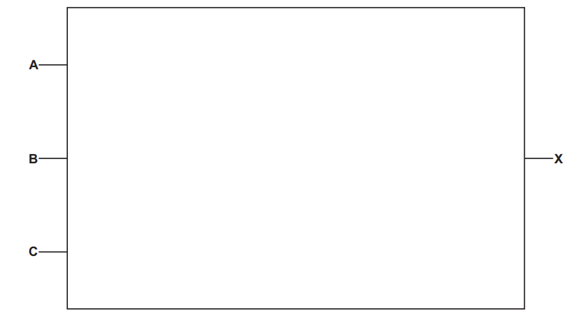
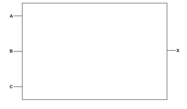
Draw the logic circuit for the logic expression:

X = ((NOT A AND (B AND C)) OR (B NAND C)) AND NOT A

Rectangle with points labelled A, B, C on the left side and X on the right side, each connected by a short line to the rectangle's edge.
4a
1 mark

Tick (✓) one box to identify the correct logic statement for this truth table.

A

B

C

X

0

0

0

1

0

0

1

0

0

1

0

0

0

1

1

0

1

0

0

0

1

0

1

0

1

1

0

1

1

1

1

0

☐ NOT (A AND B AND C)

☐ (A XOR B) NOR C

☐ (A OR B OR C) NOR C

☐ NOT A AND NOT B AND NOT C

4b
2 marks

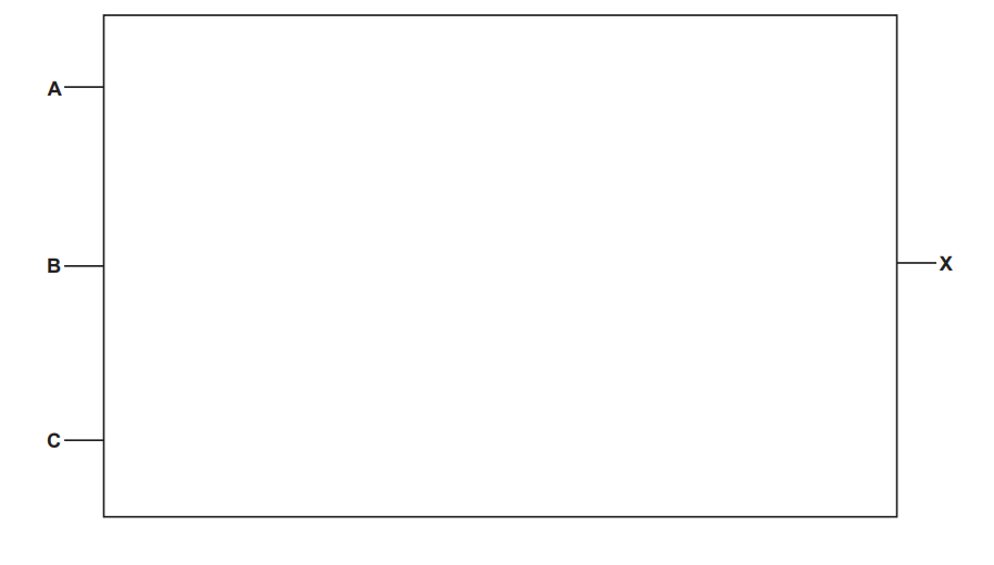
Draw a logic circuit for the logic expression:

X = NOT (NOT A AND (NOT B XOR C))

Diagram of a rectangle with labels A, B, C on the left side and X on the right side, illustrating points on the rectangle's perimeter.
5a
4 marks

Describe the operation of each of the following logic gates:

NAND .......................

NOR ........................

XOR .........................

OR ..........................

5b
2 marks

Draw a logic circuit for this logic expression:

X = NOT ((A AND B) OR (C AND D))

Diagram with a rectangle labelled A, B, C, D on the left and X on the right, indicating positions or sections within the shape.
6
3 marks

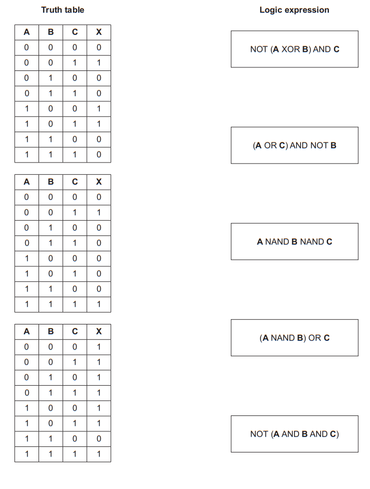
Each of the following truth tables has three inputs (A, B and C) and one output (X).

Draw one line to match each truth table with its logic expression.

Three truth tables and six logic expressions, including NOT (A XOR B) AND C and A NAND B NAND C, for comparing logical equivalence.
7
3 marks

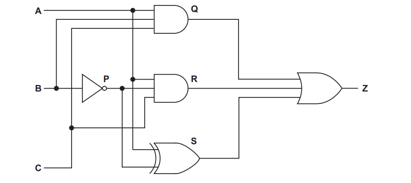
The diagram shows a logic circuit.

Logic circuit diagram with inputs A, B, C. Features NOT gate P, AND gates Q, R, S, and OR gate Z. Connections between gates are shown.

Complete the truth table for the given logic circuit. Show your working.

Working space

A

B

C

P

Q

R

S

Z

0

0

0

0

0

1

0

1

0

0

1

1

1

0

0

1

0

1

1

1

0

1

1

1

8
3 marks

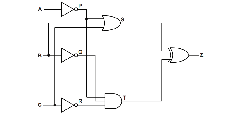
The diagram shows a logic circuit.

Logic circuit diagram with three inputs A, B, C, through NOT gates P, Q, R, leading to AND and OR gates, resulting in output Z.

Complete the truth table for the given logic circuit. Show your working.

Working space

A

B

C

P

Q

R

S

T

Z

0

0

0

0

0

1

0

1

0

0

1

1

1

0

0

1

0

1

1

1

0

1

1

1

9a
2 marks

Complete the truth table for the logic expression:

X = NOT (A NAND B) XOR (NOT B AND (B NOR C))

A

B

C

Working space

X

0

0

0

0

0

1

0

1

0

0

1

1

1

0

0

1

0

1

1

1

0

1

1

1

9b
2 marks

Draw a logic circuit for the logic expression:

X = (A AND NOT (B OR C)) AND (B NOR C)

Diagram of a rectangle with labels A, B, C on the left side and X on the right side, indicating specific points on the rectangle's perimeter.
10a
3 marks

Write the Boolean expression that corresponds to the following logic circuit.

Logic circuit diagram with inputs A, B, C. It includes NAND, OR, NOT, and AND gates. The output X is generated through these gates from inputs.
10b
2 marks

Complete the truth table for the logic expression:

X = A XOR (B AND (A NAND B) AND NOT C)

A

B

C

Working space

X

0

0

0

0

0

1

0

1

0

0

1

1

1

0

0

1

0

1

1

1

0

1

1

1

11a
2 marks

Complete the truth table for the logic expression:

Y = ((P AND Q) XOR ((NOT Q) OR R)) AND NOT P

P

Q

R

Working space

Y

0

0

0

0

0

1

0

1

0

0

1

1

1

0

0

1

0

1

1

1

0

1

1

1

11b
2 marks

Draw a logic circuit for the logic expression:

Y = ((P AND Q) XOR ((NOT Q) OR R)) AND NOT P

Diagram of a rectangle labelled P, Q, R on the left and Y on the right, with lines connecting labels to the rectangle's sides.
12
3 marks

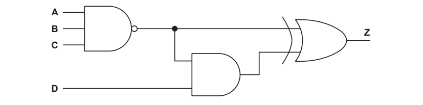
This diagram represents a logic circuit.

Logic circuit with inputs A, B, C into a NAND gate, a NOT gate, input D to an AND gate, and an OR gate producing output Z.

Complete the truth table for the given logic circuit.

A

B

C

D

Working space

Z

0

0

0

0

0

0

0

1

0

0

1

0

0

0

1

1

0

1

0

0

0

1

0

1

0

1

1

0

0

1

1

1

1

0

0

0

1

0

0

1

1

0

1

0

1

0

1

1

1

1

0

0

1

1

0

1

1

1

1

0

1

1

1

1

13
2 marks

Each logic gate below has two inputs.

Complete the table by writing the name of the logic gate that each description matches.

Description of the gate

Logic gate

The output is 1 only when the two inputs are different.

The output is 0 only when both inputs are 1.

14
3 marks

An XOR gate and an OR gate each have two inputs, A and B.

Explain how the function of the XOR gate differs from the function of the OR gate.

15
4 marks

A logic gate with two inputs, A and B, can be given four different combinations of input values.

Two of the two-input logic gates in this syllabus give an output of 1 for exactly one of these four combinations.

Identify these two logic gates. For each gate, state the input values that give the output of 1.

16
2 marks

Complete the truth table for the NOR gate.

A

B

A NOR B

0

0

0

1

1

0

1

1

Complete the truth table for the NOT gate.

A

NOT A

0

1

17
3 marks

The truth table shows the outputs of two different two-input logic gates, X and Y, for the same inputs A and B.

A

B

X

Y

0

0

1

0

0

1

1

1

1

0

1

1

1

1

0

0

Identify gate X and gate Y.

State the one combination of input values for which gate X and gate Y give different outputs.

18
4 marks

The truth table has one output column for each of three two-input logic gates.

Complete the truth table.

A

B

A AND B

A XOR B

A NAND B

0

0

0

1

1

0

1

1

Use your completed table to state which one of these three gates gives an output of 1 for the greatest number of input combinations. Give that number.

19
2 marks

A greenhouse uses an automatic water pump.

Two sensors send binary values to the control system.

Input

Binary value

Condition

M

1

The soil is dry

0

The soil is not dry

T

1

The water tank is empty

0

The water tank is not empty

The pump turns on (P = 1) when the soil is dry and the water tank is not empty.

Write the logic expression for the pump.

20
3 marks

A cutting machine in a factory is controlled by three inputs.

Input

Binary value

Condition

G

1

The safety guard is closed

0

The safety guard is open

B

1

The start button is pressed

0

The start button is not pressed

M

1

The automatic mode switch is on

0

The automatic mode switch is off

The machine starts (S = 1) when the safety guard is closed and either the start button is pressed or the automatic mode switch is on.

Complete the truth table for the machine.

G

B

M

S

0

0

0

0

0

1

0

1

0

0

1

1

1

0

0

1

0

1

1

1

0

1

1

1

State the number of input combinations for which the machine starts.

21
4 marks

A farm uses an automatic irrigation valve. Four inputs control the valve.

Input

Binary value

Condition

S

1

The soil is dry

0

The soil is not dry

R

1

Rain is detected

0

Rain is not detected

N

1

It is night

0

It is day

M

1

The manual switch is on

0

The manual switch is off

The valve opens (V = 1) when the soil is dry and rain is not detected and it is night.

The valve also opens whenever the manual switch is on, whatever the three sensors read.

The logic circuit for the valve uses four gates. Every gate except the NOT gate has two inputs. Gate 1 is the only NOT gate, and each gate may use the output of an earlier gate as one of its inputs.

Complete the table to show the circuit. Write a dash in the Input 2 column of the NOT gate.

Gate

Type of gate

Input 1

Input 2

Output

1

G1

2

G2

3

G3

4

V

22
2 marks

Complete the truth table for the logic expression:

X = (NOT A) OR B

A

B

NOT A

X

0

0

0

1

1

0

1

1

23
3 marks

A logic circuit is built from this logic expression:

Z = (A NAND B) AND (NOT C)

The circuit uses three gates. Gate 3 produces the output Z.

Complete the table to show the circuit. Write a dash in the Input 2 column of any gate that has only one input.

Gate

Type of gate

Input 1

Input 2

Output

1

G1

2

G2

3

Z

24
4 marks

A logic circuit has three inputs, A, B and C, and one output, X.

X = ((A XOR B) NAND C) AND (A OR C)

The truth table has three working columns:

  • P = A XOR B

  • Q = P NAND C

  • R = A OR C

Complete the truth table. Show your working in columns P, Q and R.

A

B

C

P

Q

R

X

0

0

0

0

0

1

0

1

0

0

1

1

1

0

0

1

0

1

1

1

0

1

1

1

25
2 marks

The truth table shows the output X of a logic circuit with two inputs, A and B.

A

B

X

0

0

0

0

1

0

1

0

1

1

1

0

Write the logic expression for X.

26
3 marks

The truth table shows the output X of a logic circuit with three inputs, A, B and C.

A

B

C

X

0

0

0

0

0

0

1

0

0

1

0

1

0

1

1

0

1

0

0

1

1

0

1

0

1

1

0

1

1

1

1

0

The circuit is built from exactly three gates: one OR gate, one NOT gate and one AND gate. Gate 3 produces the output X.

Complete the table to show the circuit. Write a dash in the Input 2 column of the gate that has only one input.

Gate

Type of gate

Input 1

Input 2

Output

1

G1

2

G2

3

X

27
4 marks

The truth table shows the output X of a logic circuit with three inputs, A, B and C.

A

B

C

X

0

0

0

0

0

0

1

0

0

1

0

0

0

1

1

1

1

0

0

0

1

0

1

1

1

1

0

0

1

1

1

0

Write the logic expression for X.

The circuit can be built from two gates. Complete the table to show that circuit.

Gate

Type of gate

Input 1

Input 2

Output

1

G1

2

X

28
2 marks

The table describes a logic circuit with three inputs, A, B and C, and one output, X.

Gate

Type of gate

Input 1

Input 2

Output

1

NOR

A

B

G1

2

AND

G1

C

X

Write the logic expression for X.

29
3 marks

The table describes a logic circuit with three inputs, A, B and C, and one output, Z.

Gate

Type of gate

Input 1

Input 2

Output

1

NOT

B

-

G1

2

XOR

A

G1

G2

3

OR

G2

C

Z

Complete the truth table for the circuit. Show your working in columns G1 and G2.

A

B

C

G1

G2

Z

0

0

0

0

0

1

0

1

0

0

1

1

1

0

0

1

0

1

1

1

0

1

1

1

30
4 marks

The table describes a logic circuit with three inputs, A, B and C, and one output, Z.

Gate

Type of gate

Input 1

Input 2

Output

1

NAND

A

B

G1

2

XOR

B

C

G2

3

AND

G1

G2

G3

4

NOR

G3

A

Z

Write the logic expression for Z.

State every combination of input values for which Z = 1.