Required Practical: The Young Modulus (AQA AS Physics): Revision Note
Exam code: 7407

Required practical: the Young modulus
Aims of the experiment
The aim of the experiment is to measure the Young modulus of a metal in the form of a wire
This requires a clamped horizontal wire over a pulley
This experiment can also be done with a vertical wire attached to the ceiling with a mass attached
Variables
Independent variable = Force (or load) (N)
Dependent variable = Extension (m)
Control variables:
The original length of wire
The thickness of the wire
The metal used for the wire
Equipment list
Equipment | Purpose |
|---|---|
Bench | To hold the equipment |
G-clamp | To stabilise the apparatus |
Copper wire | Use to calculate the Young modulus of copper |
Metre ruler | To measure the length of the wire and extension |
Pulley | To allow the mass to hang vertically, and introduces less friction than the edge of the table |
Tape marker | To accurately measure the extension with the applied load. This should touch the ruler |
Wooden blocks | Clamps together the wire to keep it taut and straight |
Mass hanger + 100 g mass | To hang from the pulley and add a load to the wire to create an extension |
Micrometer | Use to measure the diameter of the wire |
Resolution of measuring equipment:
Metre ruler = 1 mm
Micrometer = 0.001 mm
Method
This method is an example of the procedure for varying load and measuring the extension of a copper wire. This is just one way of measuring the relationship between them.
Measure the diameter of the wire with a micrometer screw gauge or digital callipers. Take at least three readings and find an average.
Set up the apparatus so the wire is taut. No masses should be on the mass hanger just yet.
Measure the original length of the wire using a metre ruler and mark a reference point with tape preferably near the beginning of the scale eg. at 1 cm.
Record initial reading on the ruler of the reference point.
Add a 100 g mass onto the mass hanger.
Read and record the new reading of the tape marker from the metre ruler.
Repeat this method by adding a 100 g mass (at least five to ten times) and record the new scale reading from the metre ruler.
An example of a table with some possible loads and extensions might look like:
Mass / g | Load / N | New marker reading / m | Extension / m |
|---|---|---|---|
100 | |||
200 | |||
300 | |||
400 | |||
500 | |||
600 |
Analysis of results
The Young modulus is found from the equation
Where:
= force (or load) (N)
= original length of the wire (m)
= cross-sectional area of the wire (m2)
= extension (m)
Rearranging the Young modulus equation for the force, :
Comparing this to the equation of a straight line: y = mx
1. Calculate the cross-sectional area of the wire
The area of circle is given by:
Where: = diameter of the wire (m)
2. Plot a graph of load (force) against extension
The load is found by multiplying each mass by (9.81 N kg–1)
3. Determine the gradient of this graph
is the gradient of the force-extension graph

4. Multiply the gradient by the ratio of the original length and cross-sectional area of the wire to calculate the Young modulus
Evaluating the experiment
Systematic Errors:
Use a vernier scale for more precise readings
This is more likely to produce an accurate value for the extension
If the wire is extended past its elastic limit, it will be permanently deformed
To reduce the risk of this, remove the load and check the wire returns to its original length before taking any new readings
Random Errors:
Parallax error from reading the marker on the ruler
Random errors are reduced by repeating the experiment for all the loads and finding an average extension
Reduce the uncertainty on the cross-sectional area by measuring the diameter in several places and calculating an average
Safety considerations
Wear safety goggles at all times in case the wire snaps
Make sure a cushion or soft surface is kept directly below the mass hanger, in case it falls off
Worked Example
A student investigates the relationship between the force on a wire and its extension. They set up the experiment by keeping the string taut with a 100 g mass. Adding on an extra 100 g each time and measuring the extension, they obtain the following table of results:
Mass / g | Load / N | Initial length / mm | Final length / mm | Extension / |
|---|---|---|---|---|
200 | 2.0 | 500 | 500.1 | 0.1 |
300 | 2.9 | 500.1 | 500.4 | 0.3 |
400 | 3.9 | 500.4 | 501.0 | 0.6 |
500 | 4.9 | 501.0 | 501.9 | 0.9 |
600 | 5.9 | 501.9 | 503.2 | 1.3 |
700 | 6.9 | 503.2 | 504.9 | 1.7 |
800 | 7.8 | 504.9 | 507.0 | 2.1 |
The following additional data for the wire is:
Length L / m | 1.382 |
Diameter 1 / mm | 0.277 |
Diameter 2 / mm | 0.280 |
Diameter 3 / mm | 0.275 |
Average diameter d / mm | 0.277 |
Cross-sectional area A / m2 |
Calculate the value of the Young modulus of the wire.
[4]
Answer:
Step 1: Plot a graph of the load (force) against the extension
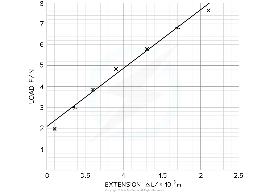
Make sure the axes are properly labelled and the line of best fit is drawn with a ruler [1 mark]
Step 2: Calculate the gradient of the graph
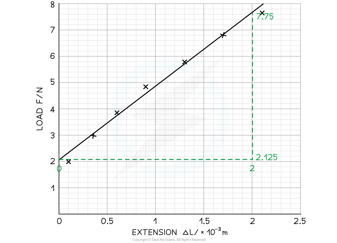
[1 mark]
Step 3: Substitute values into the Young modulus equation
Original length of wire, L = 1.382 m
Cross-sectional area, A = 6.03 × 10⁻⁸ m2
Gradient = 2812.5 N m-1
[1 mark]
[1 mark]
Examiner Tips and Tricks
Although every care should be taken to make the experiment as reliable as possible, you will be expected to suggest improvements in producing more accurate and reliable results (e.g. repeat readings and use a longer length of wire)

Unlock more, it's free!
Join the 100,000+ Students that ❤️ Save My Exams
the (exam) results speak for themselves:

Was this revision note helpful?
Build on this topic