Resistance, Resistivity & Potential Dividers (Edexcel International A Level (IAL) Physics): Exam Questions

Exam code: YPH11

35 mins7 questions
1a
Sme Calculator
1 mark

Two copper wires, W and Z, are joined as shown. Wire W has twice the diameter of wire Z.

q11-wph12-02-june-2021-edexcel-int-as-a-level-phy

W and Z are connected in series with a cell and resistor, as shown.

q11-1-wph12-02-june-2021-edexcel-int-as-a-level-phy

State the purpose of the resistor in this circuit.

1b
Sme Calculator
4 marks

The current I in a conductor is given by the formula

            I = nqvA

Complete the following table, which shows ratios of quantities for wires W and Z. The first row has been completed for you.

Ratio

Value

Reason

nwnz

1

Both wires are made of the same material

IwIz


vwvz


2a
Sme Calculator
4 marks

A filament lamp is marked 12 V 60 W. The filament is made from a long metal wire with a diameter of 0.25 mm. The metal has a resistivity of 5.6 × 10⁻⁸ Ω m when the wire is at normal operating temperature.

Calculate the length of the wire in the filament.

Length of wire = .........................................

2b
Sme Calculator
3 marks

A student has two filament lamps. Lamp A is marked 12 V 60 W and lamp B is marked 12 V 30 W. The student sets up the circuit shown.

q13b-wph12-02-oct-2021-edexcel-int-as-and-a-level-phy

The student states that both lamps will operate normally.

Evaluate whether the student’s statement is correct.

3a
Sme Calculator
2 marks

A nichrome wire of length 0.45 m has a cross-sectional area of 2.5 × 10⁻⁷ m2.

The resistance of the wire is 2.0 Ω.

Calculate the resistivity of nichrome.

Resistivity = ...................................

3b
Sme Calculator
3 marks

A potential difference of 3.0 V is applied across the nichrome wire.

Calculate the drift velocity of the conduction electrons in the nichrome wire.

number of conduction electrons per m3 = 9.0 × 1028 m–3

Drift velocity = .................................

3c
Sme Calculator
3 marks

A student suggests that the drift velocity will double if the length of wire used in the circuit is halved.

Comment on this suggestion.

4a
2 marks

A student designs a light-sensing circuit used to switch on an external circuit when the light intensity falls below a certain level.

The circuit contains a light-dependent resistor (LDR) and a fixed resistor of resistance 10 kΩ, as shown. The output potential difference (p.d.) is connected to an external circuit that contains an LED.

A potential divider circuit with a 6.0 V battery connected in series with a fixed resistor labelled "10 kΩ" and a light-dependent resistor (LDR). Wires connected across the LDR indicate it provides the output potential difference (pd) to an external circuit.

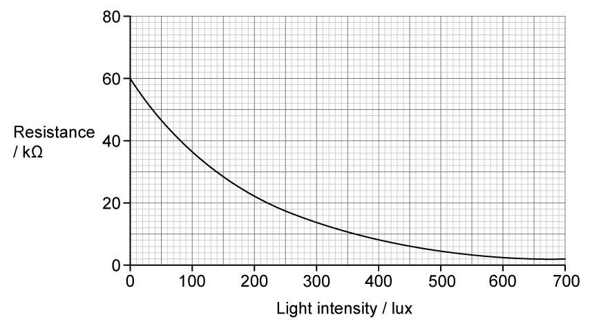
The graph shows how the resistance of the LDR varies with the incident light intensity, measured in lux.

Graph with resistance in kilohms (kΩ) on the y-axis, ranging from 0 to 80, and light intensity in lux on the x-axis, from 0 to 700.  The curve starts at a resistance of 60 kΩ at 0 lux and steadily decreases to around 2 kΩ at 700 lux.

Explain how the resistance of the LDR changes as the incident light intensity decreases.

4b
3 marks

A voltmeter is connected across the fixed resistor.

Explain what happens to the reading on the voltmeter as the incident light intensity decreases.

4c
Sme Calculator
3 marks

The LED in the external circuit switches on when the output p.d. is above 5.0 V.

Determine whether the student's circuit will switch on the LED when the incident light intensity falls below 30 lux.

5
Sme Calculator
5 marks

Early maglev prototypes used conventional copper electromagnets instead of superconducting electromagnets. Superconductors have zero resistance at low temperatures, meaning no power is wasted by transfer to thermal energy, unlike copper electromagnet systems.

The superconducting electromagnets on the SCMaglev use a liquid helium cooling system which requires a constant power of 25.0 kW.

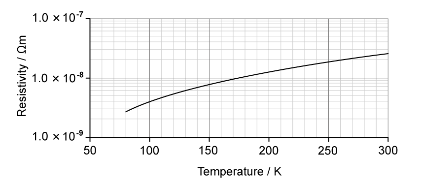
An engineer suggests that reverting to copper electromagnets operating at an average temperature of 270 K would be more efficient than superconductors because it would remove the need for the cooling system.

The graph shows the variation of resistivity with temperature for copper.

Graph of resistivity versus temperature from 50–300 K, showing resistivity rising smoothly from about 1×10⁻⁹ to 1×10⁻⁷ Ω m on a logarithmic scale.

Deduce whether the power requirement of the superconductor cooling system is less than the power losses in the copper electromagnet system.

power requirement of the copper electromagnet system=12.0 MW

operating potential difference=25.0 kV

total length of copper wire=1.50 km

cross-sectional area of copper wire=85.0 mm2