The A.C. Generator (Cambridge (CIE) IGCSE Physics): Revision Note
Exam code: 0625 & 0972

Simple a.c. generators
Extended tier only
An a.c. generator is a device which converts energy from motion into an electrical output
An alternating e.m.f. is generated which causes an alternating current to flow
A simple a.c. generator consists of
a rotating coil of wire between the poles of a permanent magnet
slip rings and brushes connected to an external circuit
Structure of a simple a.c. generator

A simple a.c. generator consists of a rotating coil in a magnetic field connected to an external circuit via slip rings and carbon brushes
The functions of each component are shown in the table:
Table of components of a simple a.c. generator
Component | Function |
|---|---|
permanent magnet | to provide a uniform magnetic field |
rotating coil | to cut the magnetic field as it rotates and allow an induced current to flow |
slip rings | to allow the alternating current to flow between the coil and the external circuit |
carbon brushes | to provide a good electrical connection between the coil and the external circuit |
Operation of an a.c. generator
A rectangular coil rotates in a uniform magnetic field
The coil is connected to an external circuit via slip rings and brushes
The induced emf in the coil can be measured by adding a galvanometer (centre-zero meter) to the external circuit
An e.m.f. is induced in the coil as it cuts the magnetic field
The pointer defects first one way, then the opposite way, and then back again
This indicates the size and direction of the emf is constantly changing
As a result of the alternating e.m.f., an alternating current is also produced as the coil rotates
This continues as long as the coil keeps turning in the same direction
Motion of an a.c. generator
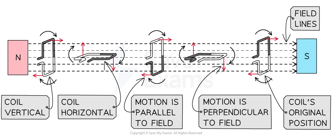
The size and direction of the induced e.m.f. (and current) depend on the orientation of the coil with the field
A maximum e.m.f. is induced when
the position of the coil is parallel to the field
the motion of the coil is perpendicular to the field
This is because the greatest number of lines are cut when the coil is moving perpendicular to the field
No e.m.f. is induced when
the position of the coil is perpendicular to the field
the motion of the coil is parallel to the field
This is because no lines are cut when the coil is moving parallel to the field
Graphs for a.c. generators
Extended tier only
The output of an a.c. generator can be seen on a graph of e.m.f. against time, or angle of rotation
The shape of the graph is a sine or cosine curve, depending on the starting position of the coil
When it starts from a horizontal position (e.m.f. is at a maximum), the graph is a cosine curve
When it starts from a vertical position (e.m.f. is zero), the graph is a sine curve
Graph of induced e.m.f. with angle for an a.c. generator
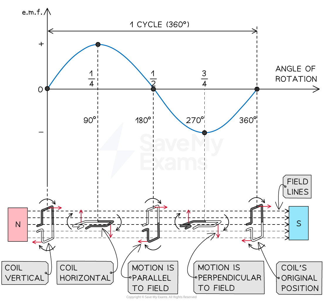
Alternating e.m.f. with corresponding positions of the coil relative to the field
When the coil is vertical at 0°
it is moving parallel to the direction of the magnetic field
the size of the induced e.m.f. is zero
When the coil has rotated by 90°
it is now horizontal and moving perpendicular to the direction of the magnetic field
the size of the induced e.m.f. is at a maximum
When the coil has rotated by 180°
it is vertical again and moving parallel to the direction of the magnetic field
the size of the induced e.m.f. is zero
When the coil has rotated by 270°
it is horizontal again and moving perpendicular to the direction of the magnetic field
the size of the induced e.m.f. is at a maximum and in the opposite direction to its position at 90°
When the coil has completed a full 360° rotation
it is back at its starting point where it is moving parallel to the direction of the magnetic field
the size of the induced e.m.f. is zero
Factor affecting a.c. generators
The magnitude of the induced e.m.f. can be increased by:
increasing the frequency of rotation of the coil
increasing the number of turns on the coil
increasing the strength of the magnet
inserting a soft iron core into the coil
Examiner Tips and Tricks
For your exam, you need to be aware that an alternating current can be produced by:
a coil rotating in a magnetic field
a magnet rotating within a coil
Both will induce an e.m.f. in the coil as they both ensure the coil will experience a changing magnetic field.
Take a look at these notes on trigonometric graphs if you need to brush up on your knowledge of sine and cosine graphs.

Unlock more, it's free!
Join the 100,000+ Students that ❤️ Save My Exams
the (exam) results speak for themselves:

Was this revision note helpful?
Build on this topic